60
6
FUNCTIONS FOR TRANSMIT
2001 NEW
■ Measuring SWR
The IC-7400 has a built-in circuit for measuring an-
tenna SWR— no external equipment or special adjust-
ments are necessary.
The IC-7400 can measure SWR in 2 ways— spot
measurement and plot measurement are available.
DD
Spot measurement
q Push [TUNER] to turn the antenna tuner OFF.
w Turn the COMP meter OFF.
➥ Push [MENU] for 1 sec. to enter set mode.
➥ Push [F1 ≤] or [F2 ≥] several times to select the
COMP Meter item.
➥
Rotate the tuning dial to set the COMP meter OFF.
➥ Push [MENU] to exit set mode.
e Push [CW/RTTY] several times to select RTTY
mode.
r Push [TRANSMIT] or [PTT] on the microphone.
t Rotate [RF PWR] clockwise past the 12 o’clock po-
sition for more than 30 W output power (30%).
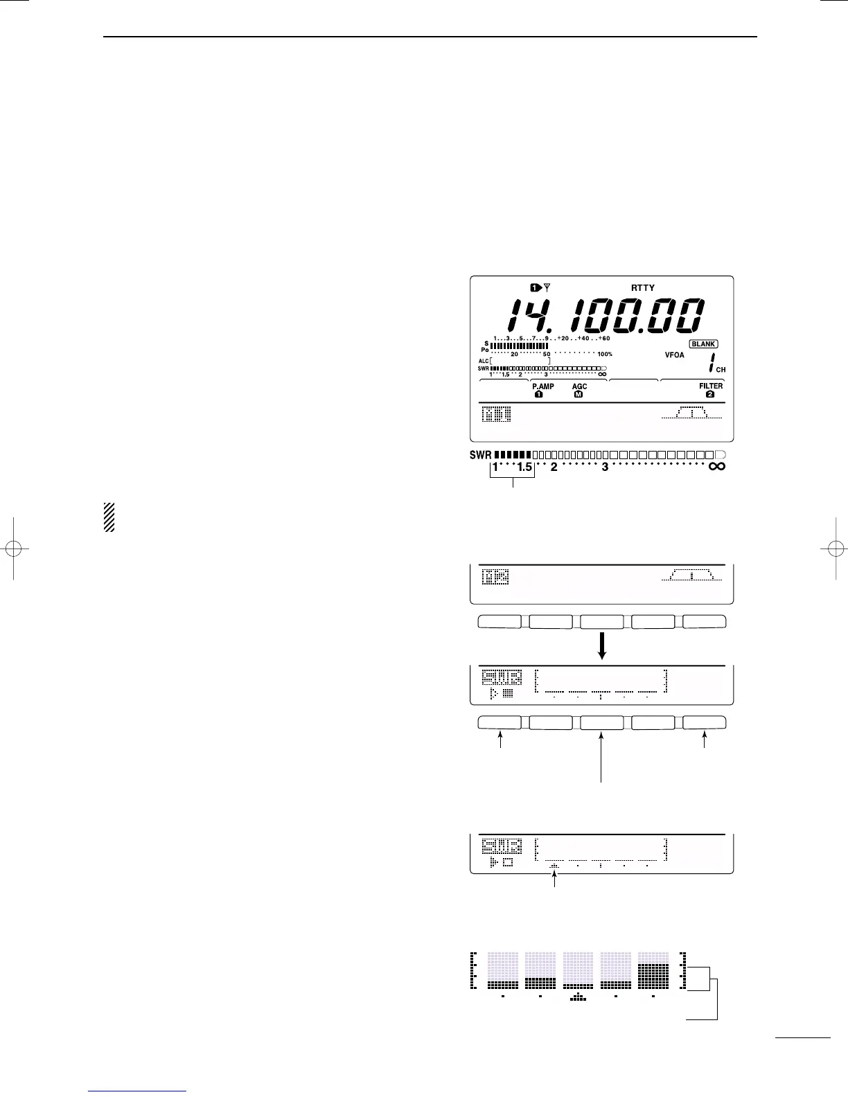
y Read the SWR on the SWR meter.
u Push [TRANSMIT] or release [PTT] to receive.
The built-in antenna tuner matches the transmitter
to the antenna when the SWR is lower than 3:1.
DD
Plot measurement
Plot measurement allows you to measure the SWR
over an entire band.
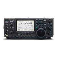
q While M2 is selected with [MENU], push [F3 SWR].
• SWR graph screen appears.
w Rotate [RF PWR] clockwise past the 12 o’clock po-
sition for more than 30 W output power (30%).
e Set the center frequency for the SWR to be mea-
sured.
r Push [F5] for 1 sec. several times to select the de-
sired measuring step from 10, 50, 100 and 500 kHz.
t Push [F3] several times to select the desired num-
ber of measuring steps from 3, 5, 7, 9, 11 and 13
steps.
y Push [F1] to start the measuring.
u Push [TRANSMIT] or push and hold [PTT] on the
microphone to measure the SWR.
• Frequency marker, “∫,” appears below SWR graph.
• RTTY mode is automatically selected.
i When pushing [TRANSMIT] again or releasing
[PTT], the frequency marker and frequency indica-
tion move to the next frequency to be measured.
o Repeat steps u and i to measure SWR over the
entire frequency range.
!0 When the measured SWR is less than 1.5:1, the
antenna is well matched with the transceiver in the
measured frequency range.
AGC
DUP
1/4
RTY
SCP
The best match is in this range.
F 1
F
2F
3
F
4
F
5
F 1
F 2 F 3 F 4 F 5
SCN
MEM
SWR
TCN
VSC
1Ok
STEP
1Ok
STEP
Push [F3]
Push [F5] to select
SWR measuring step.
Push [F3] to select number of SWR measuring steps.
Push [F1] to start
measuring.
• Measuring (after pushing [F1])
Frequency marker appears and moves after meas-
urement.
*When mesurement point/s is/are set outside of the oper-
atable frequency band, the frequency marker flashes.
Typical display SWR varying between 1 and 2,
full scale up to SWR 4.0:1.
— 1.0:1
— 1.5:1
— 2.0:1
— 3.0:1
— 4.0:1
IC-7400.qxd 02.4.2 11:35 Page 60