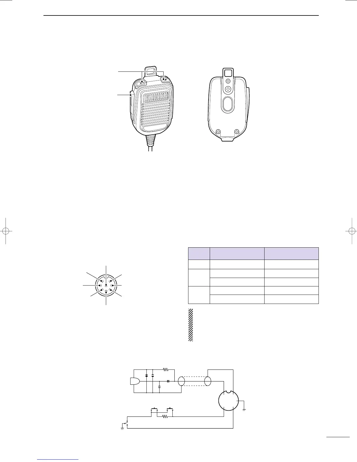
■ Microphone (HM-36)
q UP/DOWN SWITCHES [UP]/[DN]
Change the selected readout frequency or memory
channel.
•Continuous pushing changes the frequency or memory
channel number continuously.
•While pushing [XFC], the transmit readout frequency can
be controlled while in spilt frequency operation.
•The [UP]/[DN] switch can simulate a key paddle. Preset
in the keyer set mode. (p. 34)
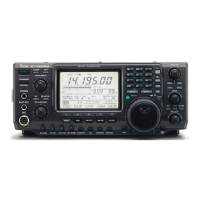
•MICROPHONE CONNECTOR
(Front panel view)
• HM-36 SCHEMATIC DIAGRAM
w PTT SWITCH
Push and hold to transmit; release to receive.
CAUTION: DO NOT short pin 2 to ground as this
can damage the internal 8 V regulator.
NOTE: DC voltage is applied to pin 1 for micro-
phone operation. Take care when using a non-Icom
microphone.
y GND (PTT ground)
t PTT
r Main readout squelch switch
q Microphone input
w +8 V DC output
e Frequency up/down
u GND
(Microphone ground)
i Main readout AF output
(varies with [AF]/[BAL])
[MIC]
FUNCTION DESCRIPTION
Pin No.
w +8 V DC output Max. 10 mA
e
Frequency up Ground
Frequency down Ground through 470 Ω
r
Squelch open “Low” level
Squelch closed “High” level
+
+
q
w
e
r
t
y
u
i
4700p
4700p
10µ
0.33µ
MICROPHONE
MIC
ELEMENT
2k
470
DOWN UP
PTT
RECEIVE
TRANSMIT
MICROPHONE CABLE MICROPHONE PLUG
12
1
PANEL DESCRIPTION
2001 NEW
IC-7400.qxd 02.4.2 11:35 Page 12