8
1
PANEL DESCRIPTION
2001 NEW
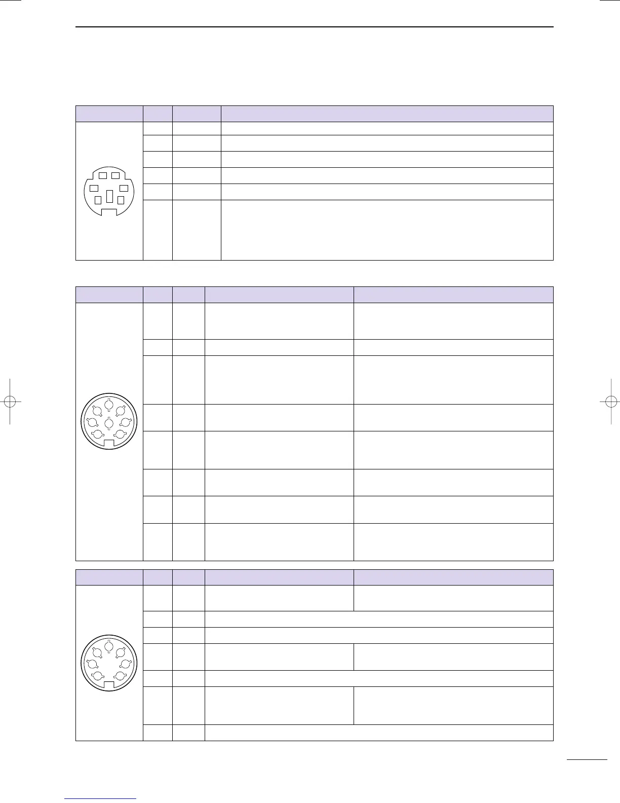
D DATA SOCKET
D ACC SOCKETS
ACC (1)
PIN No.
NAME DESCRIPTION SPECIFICATIONS
1
2
3
4
5
6
7
8
“High” level : More than 2.4 V
1 RTTY Controls RTTY keying “Low” level : Less than 0.6 V
Output current : Less than 2 mA
2 GND Connects to ground. Connected in parallel with ACC(2) pin 2.
Input/output pin.
(HF/50 MHz only)
Ground level : –0.5 V to 0.8 V
3
HSEND
Goes to ground when transmitting.
Output current : Less than 20 mA
When grounded, transmits.
Input current (Tx) : Less than 200 mA
Connected in parallel with ACC(2) pin 3.
4 MOD
Modulator input. Input impedance : 10 kΩ
Connects to a modulator. Input level : Approx. 100 mV rms
AF detector output.
Output impedance : 4.7 kΩ
5 AF Fixed, regardless of [AF] position in
Output level : 100–300 mV rms
default settings. (see notes below)
6 SQLS
Squelch output. SQL open : Less than 0.3 V/5 mA
Goes to ground when squelch opens.
SQL closed : More than 6.0 V/100 µA
7 13.8 V 13.8 V output when power is ON.
Output current : Max. 1 A
Connected in parallel with ACC(2) pin 7.
Control voltage : –4 V to 0 V
8 ALC ALC voltage input. Input impedance : More than 10 kΩ
Connected in parallel with ACC(2) pin 5.
ACC (2)
PIN No.
NAME DESCRIPTION SPECIFICATIONS
1
2
3
4
5
6
7
1 8 V Regulated 8 V output.
Output voltage : 8 V ±0.3 V
Output current : Less than 10 mA
2 GND Same as ACC(1) pin 2.
3
HSEND
Same as ACC(1) pin 3.
4 BAND
Band voltage output.
Output voltage : 0 to 8.0 V
(Varies with amateur band)
5 ALC Same as ACC (1) pin 8.
Input/output pin (144 MHz only) Ground level : –0.5 V to +0.8 V
6
VSEND
Goes to ground when transmitting. Output current : Less than 20 mA
When grounded, transmits. Input current (Tx) : Less than 200 mA
7
13.8 V
Same as ACC(1) pin 7.
Rear panel view
Rear panel view
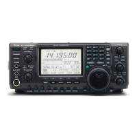
DATA
PIN No.
NAME DESCRIPTION
12
34
56
1 DATA IN Input terminal for data transmit. (1200 bps: AFSK/9600 bps: G3RUH, GMSK)
2 GND Common ground for DATA IN, DATA OUT and AF OUT.
3 PTT P PTT terminal for packet operation. Connect ground to transmit data.
4 DATA OUT Data out terminal for 9600 bps operation only.
5 AF OUT Data out terminal for 1200 bps operation only.
Squelch out terminal. Becomes high (+8 V) when the transceiver receives a signal
which opens the squelch.
6 P SQL • To avoid unnecessary TNC transmission, connect squelch to the TNC to inhibit trans-
mission when receiving signals.
• Keep audio output at a normal level, otherwise a “P SQL
”
signal will not be output.
Rear panel view
IC-7400.qxd 02.4.2 11:35 Page 8