ii
SUPPLIED ACCESSORIES
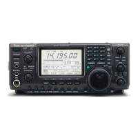
The transceiver comes with the following accessories.
Qty.
q DC power cable* ................................................ 1
w Hand microphone (HM-36) ................................ 1
e Spare fuses (FGB 30 A) .................................... 2
r Spare fuse (FGB 5 A) ........................................ 1
t CW keyer plug (AP-330) .................................... 1
*The illustration shows OPC-025D. However, OPC-639 is
supplied with versions, which “CE” symbol on the serial
number.
TABLE OF CONTENTS
FOREWORD ..................................... i
IMPORTANT ..................................... i
EXPLICIT DEFINITIONS .................. i
PRECAUTIONS ................................ i
TABLE OF CONTENTS ................... ii
QUICK REFERENCE GUIDE ..... I – X
■ Installation ....................................... I
■ Operation ....................................... III
■ Your first contact ........................... IV
■ Ready to call CQ? ......................... IX
1 PANEL DESCRIPTION ........ 1 – 12
■ Front panel ..................................... 1
■ Rear panel ...................................... 7
■ LCD display .................................... 9
■ Multi function switches .................. 11
■ Microphone (HM-36) .................... 12
2 INSTALLATION AND
CONNECTIONS ................ 13 – 17
■ Unpacking .................................... 13
■ Selecting a location ...................... 13
■ Grounding ..................................... 13
■ Antenna connection ...................... 13
■ Required connections ................... 14
■ Advanced connections ................. 15
■ Power supply connections ............ 16
■ Linear amplifier connections (not
usable in European countries)....... 17
■ External antenna tuner
connections .................................. 17
3 BASIC OPERATION .......... 18 – 25
■ When first applying power
(CPU resetting) ............................. 18
■ Initial settings ................................ 18
■ Selecting an operating band ........ 19
■ Selecting VFO/memory mode ...... 20
■ VFO operation .............................. 20
■ Frequency setting ......................... 21
■ Operating mode selection ............ 23
■ Volume setting .............................. 23
■ Squelch and receive (RF)
sensitivity ...................................... 24
■ Basic transmit operation ............... 25
4 RECEIVE AND TRANSMIT 26–45
■ Operating SSB ............................. 26
■ Operating CW ............................... 27
■ Electronic keyer functions ............ 29
■ Operating RTTY (FSK) ................. 35
■ RTTY functions ............................. 36
■ Operating AM ............................... 40
■ Operating FM ............................... 41
■ Repeater operation ....................... 44
5 FUNCTIONS FOR RECEIVE
........................................ 46 –53
■ Simple band scope ....................... 46
■ Preamp/Attenuator ....................... 47
■ RIT function .................................. 47
■ AGC function ................................ 48
■ IF filter selection ........................... 49
■ IF (DSP) filter shape ..................... 50
■ Noise blanker ............................... 50
■ Meter peak hold function .............. 50
■ Twin PBT operation ...................... 51
■ Noise reduction ............................ 52
■ Notch function .............................. 52
■ Dial lock function .......................... 52
■ Voice squelch control function ...... 53
6 FUNCTIONS FOR TRANSMIT
............................................ 54 –60
■ VOX function ................................ 54
■ Break-in function .......................... 55
■ ∂TX function ................................ 56
■ Monitor function ............................ 56
■ Speech compressor ..................... 57
■ Transmit filter width selection ....... 57
■ Split frequency operation .............. 58
■ Quick split function ....................... 59
■ Measuring SWR ........................... 60
7 MEMORY OPERATION ..... 61 – 67
■ Memory channels ......................... 61
■ Memory channel selection ............ 61
■ Programming a memory ............... 62
■ Memory clearing ........................... 62
■ Selecting the call channel ............. 63
■ Programming the call channel ...... 63
■ Frequency transferring ................. 64
■ Programming scan edges ............ 65
■ Assigning memory names ............ 66
■ Memo pads ................................... 67
8 SCANS .............................. 68 – 73
■ Scan types .................................... 68
■ Preparation ................................... 68
■ Voice squelch control function ...... 69
■ Scan set mode ............................. 69
■ Programmed scan/Fine programmed
scan .............................................. 70
■ Memory scan operation ................ 71
■ Select memory scan ..................... 71
■ ∂F scan operation and Fine ∂F scan
...................................................... 72
■ Tone scan/DTCS code scan
operation ...................................... 73
9 ANTENNA TUNER OPERATION
......................................... 74–76
■ Antenna connection and selection 74
■ Antenna tuner operation ............... 75
■ Optional external tuner operation . 76
10 DATA COMMUNICATION .. 77– 79
■ Connections ................................. 77
■ Packet (AFSK) operation .............. 78
■ Adjusting the TNC output level ..... 79
■ Data transmission speed .............. 79
11 SET MODE ......................... 80–88
■ General set mode ......................... 80
■ Tone control set mode .................. 88
12 OPTION INSTALLATION .. 89 – 90
■ Opening the transceiver’s case .... 89
■ UT-102
VOICE SYNTHESIZER UNIT
... 89
■ CR-338
HIGH STABILITY CRYSTAL UNIT
..................................................... 90
13 MAINTENANCE ................. 91–93
■ Trouble shooting ........................... 91
■ Fuse replacement ......................... 92
■ Tuning dial brake adjustment ....... 92
■ Resetting the CPU ........................ 93
■ Frequency calibration (approximate)
..................................................... 93
14 CONTROL COMMAND ...... 94–98
■ Remote jack (CI-V) information .... 94
15 SPECIFICATIONS ..................... 99
16 OPTIONS................................. 100
17 ABOUT CE ...................... 101–102
Icom, Icom Inc. and the logo are registered trademarks of Icom Incorporated (Japan) in the United States, the United King-
dom, Germany, France, Spain, Russia and/or other countries.
2001 NEW
IC-7400.qxd 02.4.2 11:34 Page 3