2001 NEW
17
2
INSTALLATION AND CONNECTIONS
2001 NEW
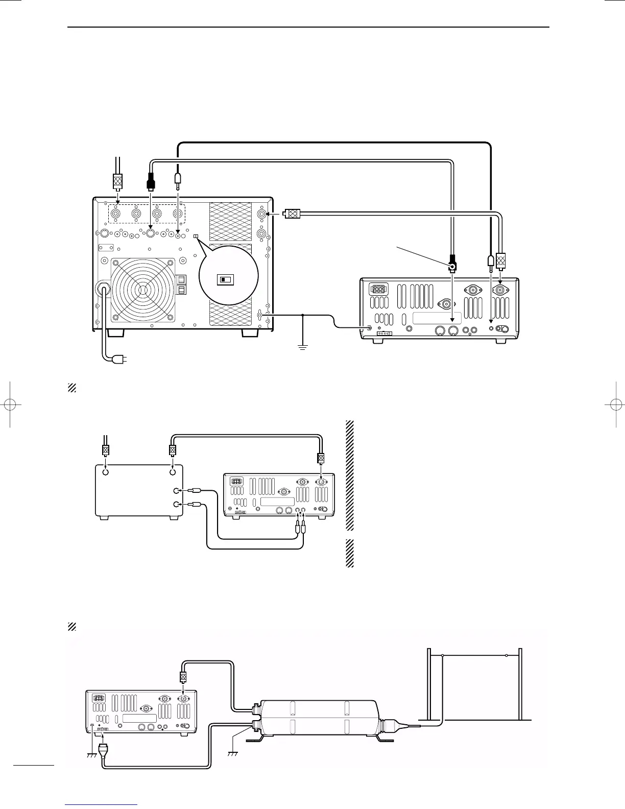
■ Linear amplifier connections (not usable in European countries)
CONNECTING THE IC-PW1
Turn OFF the transceiver’s antenna tuner while tuning the IC-PW1’s tuner.
CONNECTING A NON-ICOM LINEAR AMPLIFIER
R WARNING:
Set the transceiver output power and linear ampli-
fier ALC output level referring to the linear amplifier
instruction manual. Be sure the linear amplifier key-
ing circuit control voltage is compatible with the IC-
746PRO, before connecting to [SEND] jack.
The ALC input level must be in the range 0 V to –4
V, and the transceiver does not accept positive volt-
age. Non-matched ALC and RF power settings
could cause a fire or ruin the linear amplifier.
The specifications for the SEND relay are 16 V/DC
0.5 A. If this level is exceeded, a large external
relay must be used.
■ External antenna tuner connection
CONNECTING THE AH-4
The AH-4 must be connected to [ANT1].
To an
antenna
ACC(1)
ANT
ANT1
ACC(2)
INPUT1
REMOTE
EXCITER
1
1&2
GND
GND
IC-PW1
AC outlet
(Non-European versions: 100—120/220—240 V
European version : 230 V)
Ground
Transceiver
REMOTE
Remote control cable (supplied with the IC-PW1)
ACC cable (supplied with the IC-PW1)
Be sure to connect the cable
to the 7-pin ACC(2) jack.
Coaxial cable
(supplied with the IC-PW1)
Coaxial cable (from AH-4)
ANT1
Transceiver
Ground
AH-4
Control cable
Long wire or optional AH-2b
50 Ω coaxial cable
Non-Icom linear amplifier
SEND
ALC
To an
antenna
RF OUTPUT RF INPUT
ALC
SEND
ANT1
Transceiver
Use the [ANT1] connector when connecting a linear amplifier.
IC-7400.qxd 02.4.2 11:35 Page 17