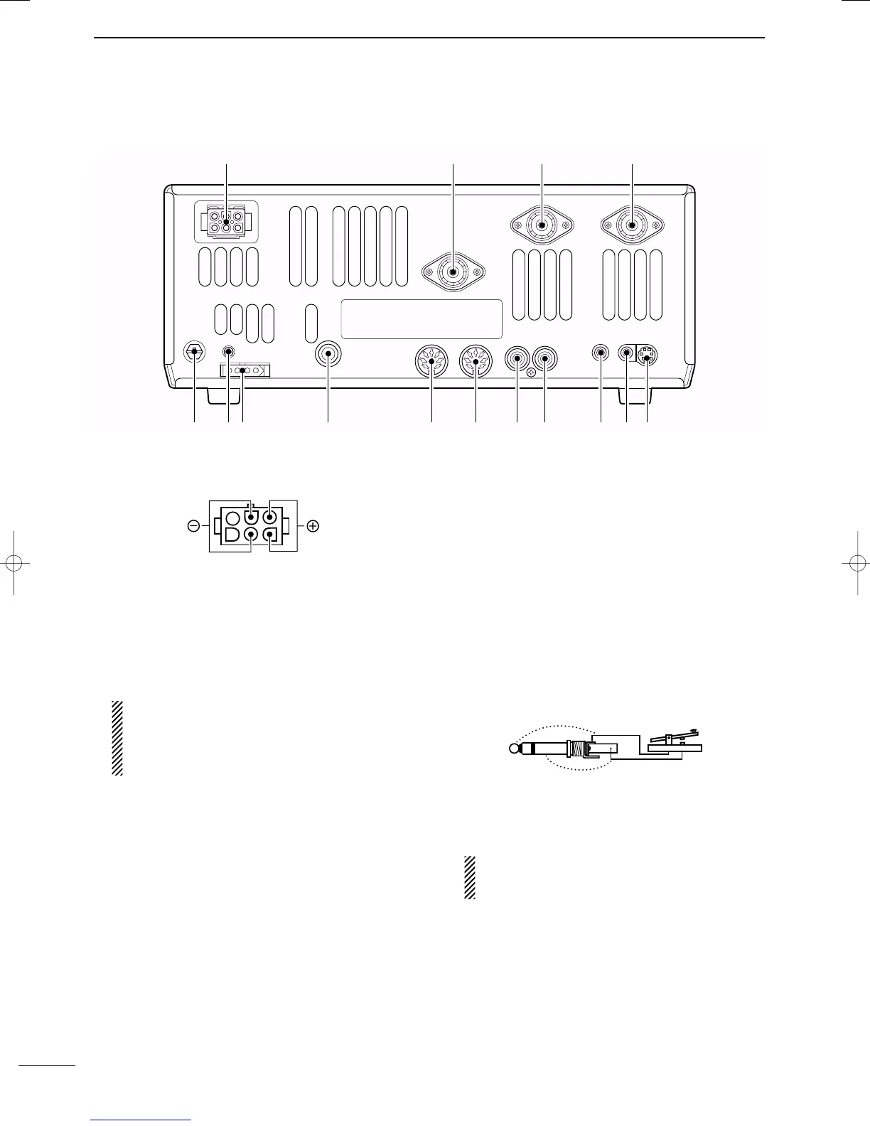
■ Rear panel
!5 !3 t
r
!2 !1 !0 oi uy
qwe
!4
7
1
PANEL DESCRIPTION
2001 NEW 2001 NEW
q DC POWER SOCKET [DC 13.8V] (pgs. 14, 16)
Accepts 13.8 V DC through the supplied DC power
cable (OPC-025D).
w ANTENNA CONNECTOR [ANT 144MHz]
e ANTENNA CONNECTOR 2 [ANT2]
r ANTENNA CONNECTOR 1 [ANT1]
(pgs. 14, 15, 17, 75)
Accepts a 50 Ω antenna with a PL-259 connector.
•[ANT 144MHz] for 144 MHz (2 m) band only; [ANT1] and
[ANT2] for both HF and 50 MHz (6 m) bands antennas.
When using an optional AH-4 HF/50 MHz AUTO-
MATIC ANTENNA TUNER
, connect it to the [ANT1]
connector. The internal antenna tuner activates
for [ANT2] and deactivates for [ANT1] when con-
necting the AH-4.
t DATA SOCKET [DATA] (pgs. 15, 78)
Connects a TNC (Terminal Node Controller), etc. for
data communications.
• See p. 8 for connector information.
y
EXTERNAL SPEAKER JACK [EXT SP] (pgs. 15, 101)
Accepts a 4–8 Ω speaker.
u
CI-V REMOTE CONTROL JACK [REMOTE] (p. 95)
➥ Designed for use with a personal computer for re-
mote control of the transceiver functions.
➥ Used for transceive operation with another Icom
CI-V transceiver or receiver.
i SEND CONTROL JACK [SEND] (p. 17)
Goes to ground while transmitting to control exter-
nal equipment such as a linear amplifier.
• Max. control level: 16 V DC/0.5 A
CAUTION: Be sure the linear amplifiers keying cir-
cuit control voltage is compatible to the IC-746PRO,
before connecting to [SEND].
o ALC INPUT JACK [ALC] (p. 17)
Connects to the ALC output jack of a non-Icom lin-
ear amplifier.
!0 ACCESSORY SOCKET 2 [ACC(2)]
!1 ACCESSORY SOCKET 1 [ACC(1)]
Enables connection of external equipment such as
a linear amplifier, an automatic antenna selector/
tuner, TNC for data communications, etc.
• See p. 8 for socket information.
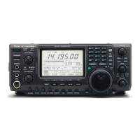
!2 STRAIGHT KEY JACK [KEY] (p. 14)
Accepts a straight key or external electronic keyer
with
1
⁄4 inch standard plug.
•[ELEC-KEY] on the front panel can be used for a straight
key or external electronic keyer. Deactivate the internal
electronic keyer in keyer set mode. (p. 34)
!3 TUNER CONTROL SOCKET [TUNER]
(pgs. 15, 77)
Accepts the control cable from an optional AH-4
HF/50 MHz AUTOMATIC ANTENNA TUNER.
If you use an external electronic keyer, make
sure the voltage retained by the keyer is less
than 0.4 V when the key is ON.
!4 CALIBRATION POT [CAL] (p. 94)
This is used for frequency calibration.
•The transceiver has been adjusted and calibrated thor-
oughly at the factory. Under normal circumstances, the
frequency does not need to be re-calibrated.
!5 GROUND TERMINAL [GND] (pgs. 13, 14)
Connect this terminal to a ground to prevent electri-
cal shocks, TVI, BCI and other problems.
IC-7400.qxd 02.4.2 11:35 Page 7