w
q
e
r
t
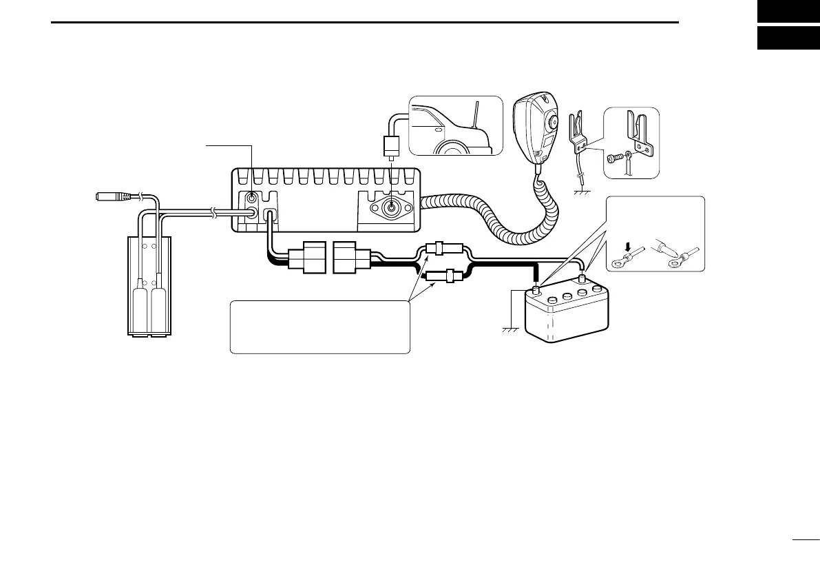
black: _
red: +
External speaker jack
OPC-871 HEADSET
ADAPTER (Option)
Antenna
Supplied DC
power cable
12 V or 24 V
Battery
12 V or 24 V
Battery
RWARNING! NEVER remove the fuse-
holders from the DC power cable.
(Depending on version, the fuse holder
may not be attached to the black cable.)
Solder
Crimp
NOTE: Use the termi-
nals as shown for the
cable connections.
6
CONNECTION AND INSTALLATION
12
■ Rear panel and connections
q Connects to an antenna
Ask your dealer about antenna selection and best installa-
tion location. (Standard 50 Ω antenna with an SWR <3.0)
w MICROPHONE HANGER
Connect the supplied microphone hanger to the vehicle’s
ground to use the hanger scan function when hanging or
removing the microphone.
e DC POWER RECEPTACLE
Connects to a 12 or 24 V DC battery. Pay attention to po-
larities.
RWARNING! NEVER connect to a over 27.5 V battery.
This could damage the transceiver.
r EXTERNAL SPEAKER JACK
Connect an 8 Ω, 30 W (Min.) external speaker, if desired.
CAUTION: DO NOT use an external speaker whose
power input rating is less than 30 W or whose impedance
is less than 8 Ω. Using a speaker of less than 30 W power
rating, or less than 8 Ω impedance, could cause damage
to the external speaker or to the transceiver itself.
t OPC-871 OPTIONAL HEADSET ADAPTER
Connect an optional headset. (See p. 16)

 Loading...