3
1
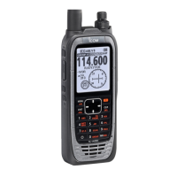
PANEL DESCRIPTION
■ Function display
q MEMORY MODE INDICATOR (p. 4)
Appears when the Memory mode is selected.
w DUALWATCH INDICATOR (p. 7)
Appears when the dualwatch function is activated.
e SCAN INDICATOR (p. 6)
Appears when the scan function is selected.
r BUSY INDICATOR (pp. 4, 5)
Appears when receiving a signal or when the squelch is
open.
t TX INDICATOR (p. 4)
Appears while transmitting.
y FREQUENCY DISPLAY
➥ Shows the operating frequency. (p. 4)
➥ Shows the channel name when the memory name func-
tion is selected. (p. 10)
u VOLUME LEVEL INDICATORS
Shows the AF volume level (while receiving).
i SET MODE INDICATOR (p. 10)
Appears when the Initial Set mode is selected.
o LOCK OUT INDICATOR (p. 8)
Appears when the channel is set as a ‘LOCK OUT’ chan-
nel.
!0 MEMORY CHANNEL INDICATOR
➥ Displays the selected memory channel number
➥“Pr”appearswhentheprioritychannelisselected.
*NOTE: The VFO/memory switch [V/M] and the memory
write switch [MW](V/M) functions may not be available,
depending on the version.
 Loading...