17
8
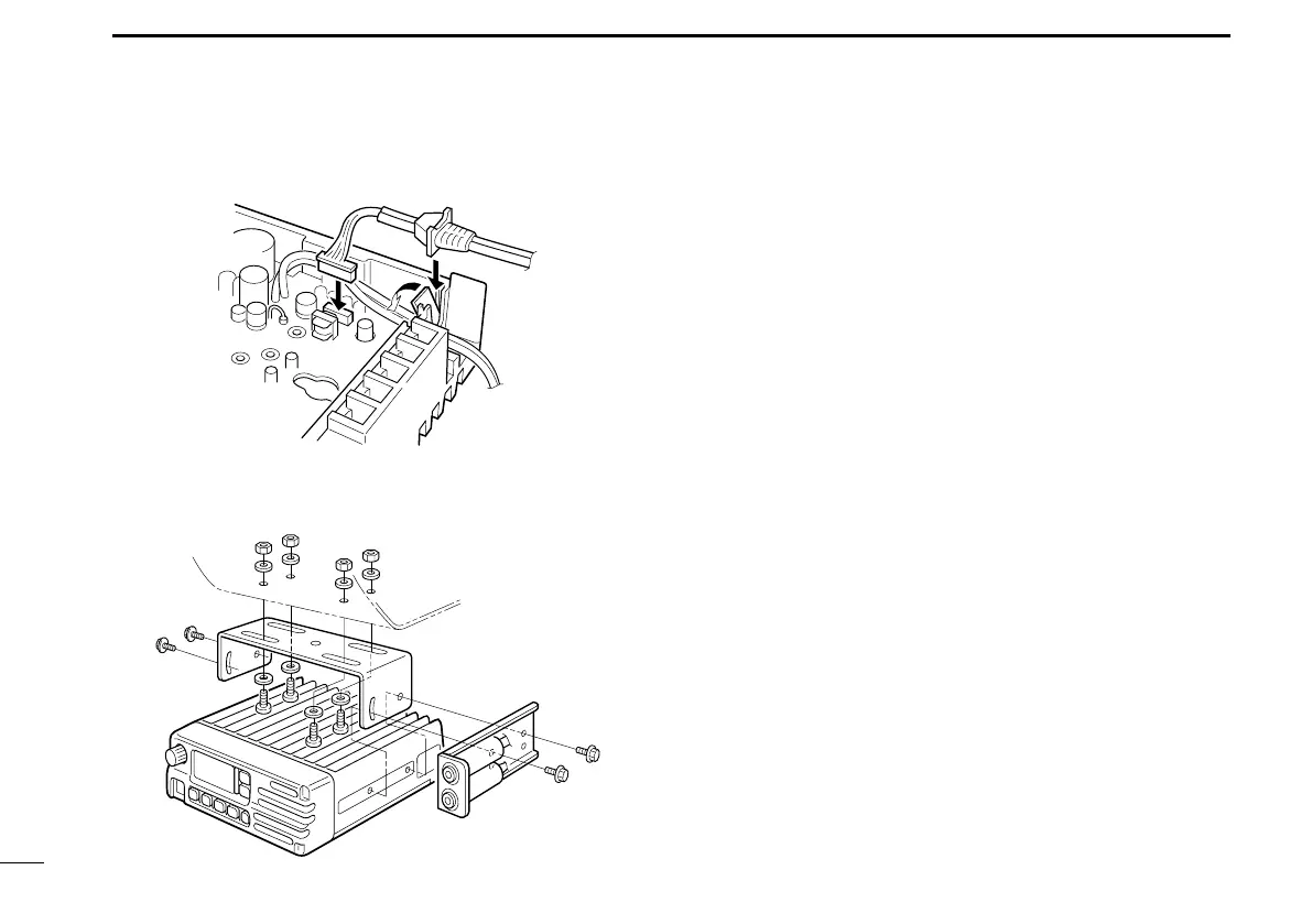
OPTIONS
•Usetheuppersidemountinghole.
•Youcanmounttheattachmentoneithersideofthetrans-
ceiver.
•Bendtheplasticdustcoverdownbeforeinstallingthestrain
relief into the notch.
Fig. 2
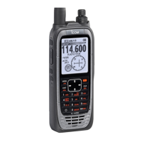
Fig. 3
■ Other options
OPC-871 HEADSET ADAPTER (Also see p. 16)
CS-A110EURO
CLONING SOFTWARE
Provides quick and easy programming of items, including pri-
vate channels, scan settings, etc. to the transceiver, using a
PC.
OPC-478
CLONING CABLE
OPC-592
CLONING CABLE ADAPTER
These three components work as one set and provide for
quick and easy programming of items, including memory
channels, memory names and set mode contents, etc. with
a PC.
Approved Icom optional equipment is designed for optimal perfor-
mance when used with an Icom transceiver.
Icom is not responsible for the destruction or damage to an Icom
transceiver in the event the Icom transceiver is used with equipment
that is not manufactured or approved by Icom.