New2001
n Connections
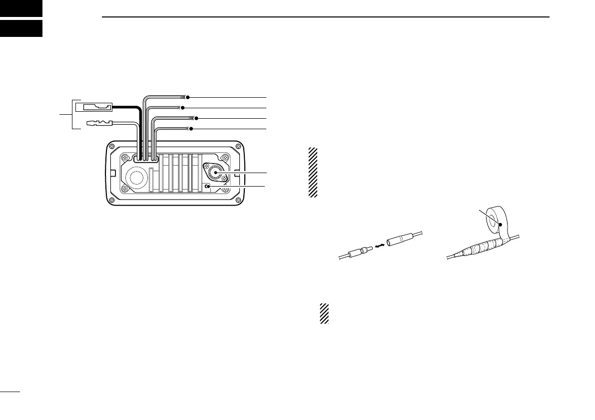
q DC POWER CONNECTOR
Connect the supplied DC power cable from this connector
to an external 12 V battery.
w EXTERNAL SPEAKER LEAD (Yellow)
Connect an external speaker.
e CLONE LEAD (Blue)
Connect a cloning cable.
r NMEA IN LEAD (Red)
Connect a GPS receiver for position indication.
•ANMEA0183ver.2.0or3.01(sentenceformattersRMC,GGA,
GNS, GLL) compatible GPS receiver is required. Ask your
dealer about suitable GPS receivers.
t NMEA OUT LEAD (White)
Connect a PC or navigation equipment (NMEA0183
ver. 3.01 sentence formatters DSC, DSE compatible) for
plotting position data received from other ships.
CAUTION: After connecting the DC power cable, NMEA
IN/OUT leads, external speaker lead and clone lead,
cover the connector and leads with rubber vulcanzing
tape, as shown below, to prevent water seeping into the
transceiver.
y ANTENNA CONNECTOR
Connect a marine VHF antenna with a PL-259 connector
to the transceiver.
CAUTION: Transmitting without an antenna may dam-
age the transceiver.
u GROUND TERMINAL
Connect this terminal to a vessel ground to prevent elec-
trical shocks and interference from other equipment oc-
curring. Use a PH M3 × 6 mm screw (not supplied).
48
New2001
CONNECTIONS AND MAINTENANCE
8