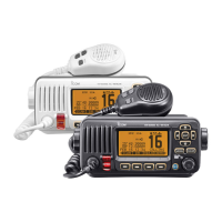
How to turn on beep sounds on Icom Transceiver?
- SStacey KellySep 7, 2025
If you are not hearing any beep sounds on your Icom Transceiver, it is likely that the beep tones are turned off. Go to the CONFIGURATION menu and turn the beep tones ON.

How to turn on beep sounds on Icom Transceiver?
If you are not hearing any beep sounds on your Icom Transceiver, it is likely that the beep tones are turned off. Go to the CONFIGURATION menu and turn the beep tones ON.
| Type | Marine VHF Transceiver |
|---|---|
| Frequency Range | 156.000 - 163.425 MHz |
| Waterproof Rating | IPX7 |
| Display | LCD |
| GPS | No |
| DSC | Yes |
| Power Supply | 13.8 V DC |
| Modulation | FM |
| Current Consumption | 1.5 A (max) |
| Output Power | 25W |
Defines terms used in the manual, including warnings and notes.
Procedure for distress calls using Channel 16.
Procedure for distress calls using Digital Selective Calling.
Describes the front panel layout and controls of the transceiver.
Explains the icons and information shown on the transceiver's display.
Details the speaker microphone functions and connections.
Explains how softkey functions are assigned and used.
Guide to programming the Maritime Mobile Service Identity (MMSI) code.
How to select operating channels, including Channel 16 and Call channels.
Instructions for receiving signals and transmitting messages.
How to program a specific Call channel for quick recall.
How to assign a name to a specific channel.
How to enable or disable the microphone lock function.
How to adjust the audio volume level of the transceiver.
How to adjust the squelch level for optimal signal reception.
How to adjust the brightness of the LCD and key backlight.
Function to clear water from the speaker grill.
Explains Priority and Normal scan modes for efficient signal locating.
How to add or clear channels for efficient scanning.
Steps to initiate Priority or Normal scans.
Explains Dualwatch and Tri-watch for monitoring Channel 16 and Call channel.
How to select and start Dualwatch or Tri-watch modes.
How to program and manage individual and group DSC address IDs.
Procedure for programming Group IDs for DSC calls.
Steps to delete programmed Individual or Group DSC IDs.
Manually inputting ship's position and UTC time for distress calls.
Procedure for transmitting distress calls via DSC.
How to send various types of DSC calls to specific stations.
Procedures for receiving and responding to DSC calls.
Accessing and managing stored received DSC messages.
Accessing and managing stored transmitted DSC calls.
Configuring various DSC operational parameters and functions.
Setting how the transceiver handles Channel 16 after a distress call.
Configuring DSC data output to connected devices.
Setting alarm functions for different DSC categories or statuses.
Adjusting the squelch level for Channel 70.
Performing a loop test to check DSC transmit and receive circuits.
Transmitting DSC calls to AIS targets via the transponder.
How to use the intercom function with the optional microphone.
How to output received audio to an external PA speaker.
How to use the PA function for announcements through a PA speaker.
How to activate the horn function.
Overview of using the menu screen for settings and calls.
Step-by-step guide to navigating and operating the menu screen.
Lists all available items and their page references within the menu system.
Details on initiating and managing individual DSC calls.
Configuration for GPS position input in DSC settings.
Selection of Normal scan or Priority scan modes.
Adjustment of the LCD and key backlight brightness.
Displays programmed MMSI code and GPS information.
Setting scan pause behavior for Normal and Priority scans.
Option to select Dualwatch or Tri-watch monitoring modes.
Selection of appropriate channel groups (USA, INT, CAN).
Setting up weather alert tones and scanning of weather channels.
Assigning functions to Dial and softkeys for customized operation.
Assigning functions to softkey buttons for quick access.
Setting the local time offset from UTC.
Adjusting noise reduction for receive and transmit signals.
Setting automatic return to normal screen after periods of inactivity.
Setting a Remote ID number for NMEA format.
Selecting internal or external speaker for the COMMANDMIC.
Diagrams and descriptions of all transceiver connection ports.
Connecting the transceiver to a 13.8 V DC power source.
Connecting to a vessel ground for safety and interference reduction.
Jack for connecting the optional Command microphone.
Connecting the transceiver to the MA-500TR AIS transponder.
Importance of antenna selection and mounting for performance.
Procedure for replacing a blown fuse in the DC power cable.
How to clean the transceiver using a soft, dry cloth.
List of items included in the transceiver package.
Instructions for mounting the transceiver using the supplied bracket.
Guide for flush mounting the transceiver using the MB-132 kit.
Instructions for installing the HM-195 Command microphone and its cable.
Technical details of the transceiver's general, transmitter, and receiver performance.
List and description of optional accessories available for the transceiver.