Model 252
Label Printer/Applicator
Operators/Technical Manual
25
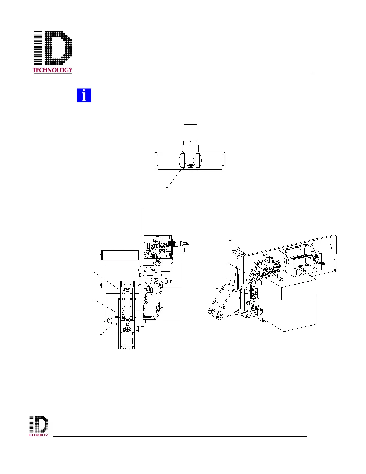
The flow controls must be installed correctly to provide the necessary speed
control of the swing action. Incorrect installation will result in improper
operation.
With the air cylinder extended, install the yellow tube in the fitting located on the tamp
pad. Route the tubing to the rear of the applicator through the provided access holes and
plug the tube into the “Y” fitting on the pneumatic assembly. Push the grey tube over the
end of the barb fitting on the lower end of the air cylinder until approximately 1/4 to 3/8
inch of the barb fitting is inside the grey tube. Push the black tube over the end of the
barb fitting on the upper end of the air cylinder until approximately 1/4 to 3/8 inch of the
barb fitting is inside the black tube. Route the grey and black tubes through the access
TO AIR CYLINDER
TO SOLENOID VALVE
LARGE ARROW
SIDE
GREY TUBING
BLACK TUBING (1/4")
YELLOW TUBING
(2) FLOW
CONTROLS
BLACK TUBING (1/4")
GREY TUBING
YELLOW TUBING