Model 252
Label Printer/Applicator
Operators/Technical Manual
26
hole (with the yellow tube) to the back of the applicator. A color cap on the fittings will
aid in selecting the correct port or fitting to connect the tubes to. Plug the black and grey
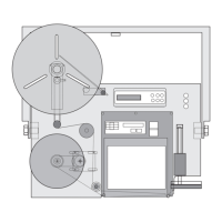
tubes into the color-coded fittings on the pneumatic manifold. By hand, push the tamp
pad to the non-extended position and back to the extended position. Ensure that the
black, grey, and yellow tubes are not restricted or pinched in any way. Position a flow
control along the black tube in the approximate location of the tampjet solenoid valve
mounting. Cut the tubing in two and insert the flow control in between the two ends
observing the proper arrow orientation as indicated in the diagram. Repeat the process to
install the flow control in the grey tube. Again, by hand, push the tamp pad to the non-
extended position and back to the extended position. Ensure that the black, grey, and
yellow tubes are not restricted or pinched in any way. It may be necessary to trim the
tubing lengths for the best routing option. Replace the back cover and reconnect any
cables disconnected during removal.