8 HARDWARE CONFIGURATION
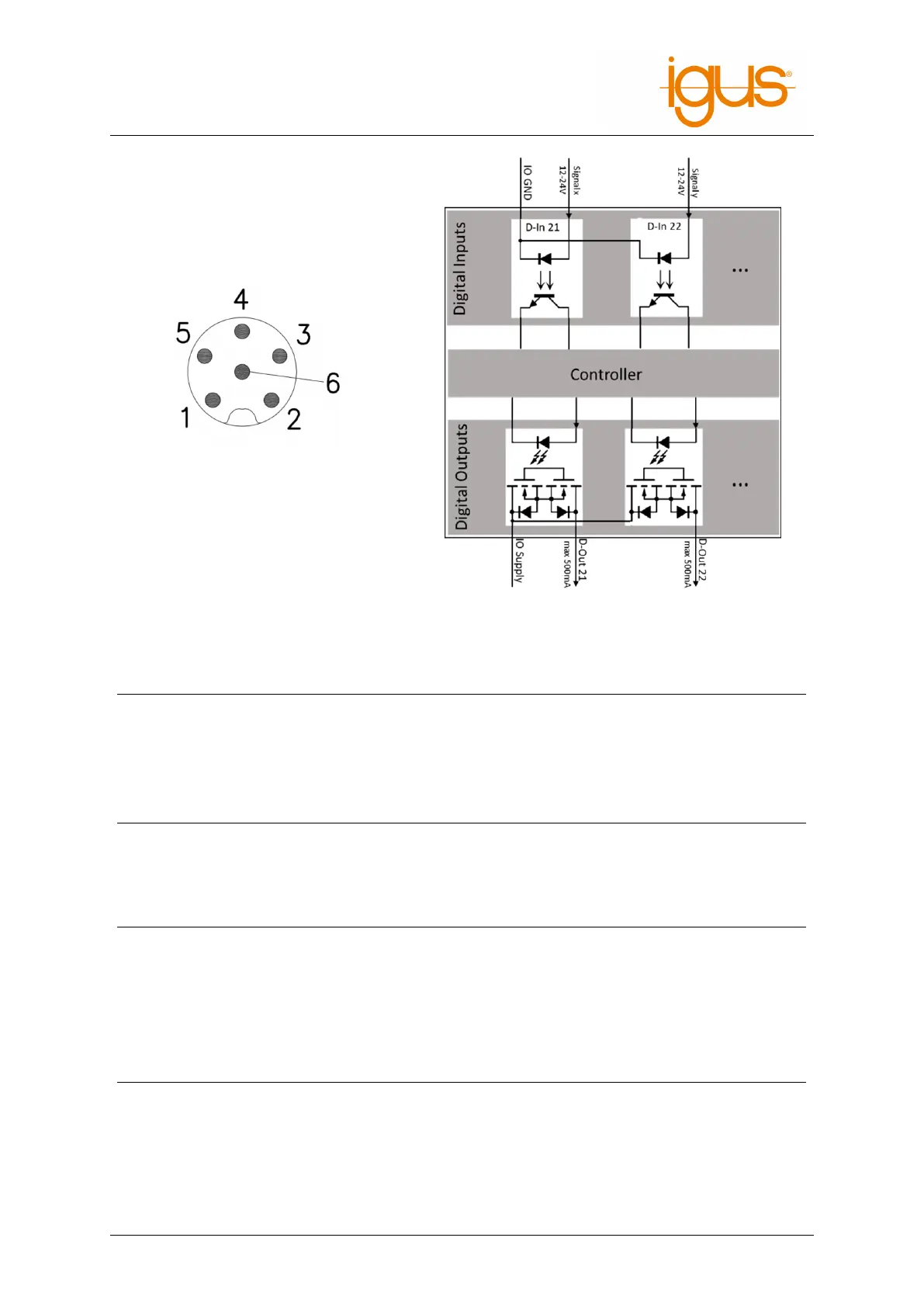
Figure 24: Pinout of the DIO socket on the
arm
Figure 25: Internal structure of a DIO module
Pin Belegung
1 DIn21
2 DIn22
3 DIn23
4 DIn34
5 External GND
Table 7: Pinout of the DIO socket at the base (left to right)
Pin Function Cable color (according to binder cables)
1 +24VDC (max 500mA) Brown
2 DIn32 White
3 GND Blue
4 DIn31 Black
5 DOut32 Gray
6 DOut31 Pink
Table 8: Pinout of the DIO socket on the arm (see fig. 24)
8.1.2 Software-Configuration
The software and integrated control are preconfigured for the two DIO modules of the Rebel.
©2022 igus® GmbH 37