MAGIS COMBO PLUS V2
17
0
10
20
30
40
50
60
70
80
0 200
400
600 800 1000 1200 1400 1600
1800
0
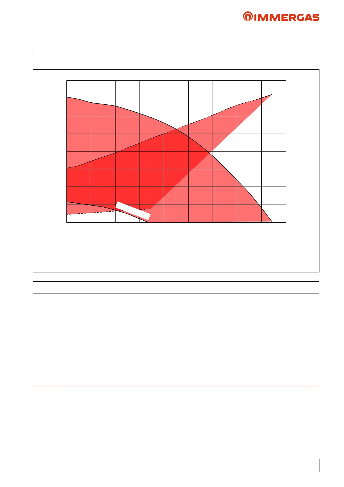
Max. Speed (100%)
Min Speed (45%)
TECHNICAL NOTE: System minimum water content:
To facilitate proper execution of the heat pump defrost cycles, a minimum water content in the system is required, which must be 30 litres
for all kinds of system. So attention must be paid to the systems divided over several zones, where the water content available to the machine
changes continuously. is is why it may be necessary to provide a heating ywheel that guarantees normal operation with systems divided
into zones (with variable water content in circulation). is minimum content also guarantees proper operation with fan coils used for
cooling (a condition in which the ow temperature is very low and has signicant heat load variations that vary the number of active fan
coils). It is also important to check that the dehumidier line has a minimum of 3 l/kW of the machine (dehumidier hydraulic circuit
connection).
EEI ≤ 0.20 - Part 3
B
A
NOTE: for proper system operation, make sure that the
minimum ow rate in operating conditions never drops
below 500 l/h.
Treating the feed water allows you to prevent problems and
maintain the function and eciency of the generator over
time.
Legislative Decree 26/06/2015 requires a chemical treatment
of the thermal system water, in compliance with the UNI 8065
standard, in the cases provided for by the Decree.
Flow rate (l/h)
Pump absorbed power (W)
KEY:
A = Head available to the system
B = Absorbed power by the circulator (dotted area)
Head (kPa)
e indoor units are equipped with low power consumption
pump with variable speed control associated with the heat pump
operation (chiller circuit).
e pump speed is set via the following parameters:
Fixed ("A 05" = 0): the circulator speed is xed and corresponds
to the settings made through the “A 04” parameter.
∆T constant ("A 05" = 5 ÷ 25 K): the pump speed varies to
maintain the ∆T (5K) constant between the system ow and
return. Also, you can adjust the pump operating range, by set-
ting the maximum speed through the “A 04” parameter and the
minimum speed through the “A 03” parameter.
12.3 GRUNDFOS UPM3 K 1575 PUMP SETTINGS AND CONFIGURATIONS
12.2 GRAPH OF HEAT PUMP FLOW RATE/HEAD