MAGIS COMBO V2
7
Casing upper line
A AA/S
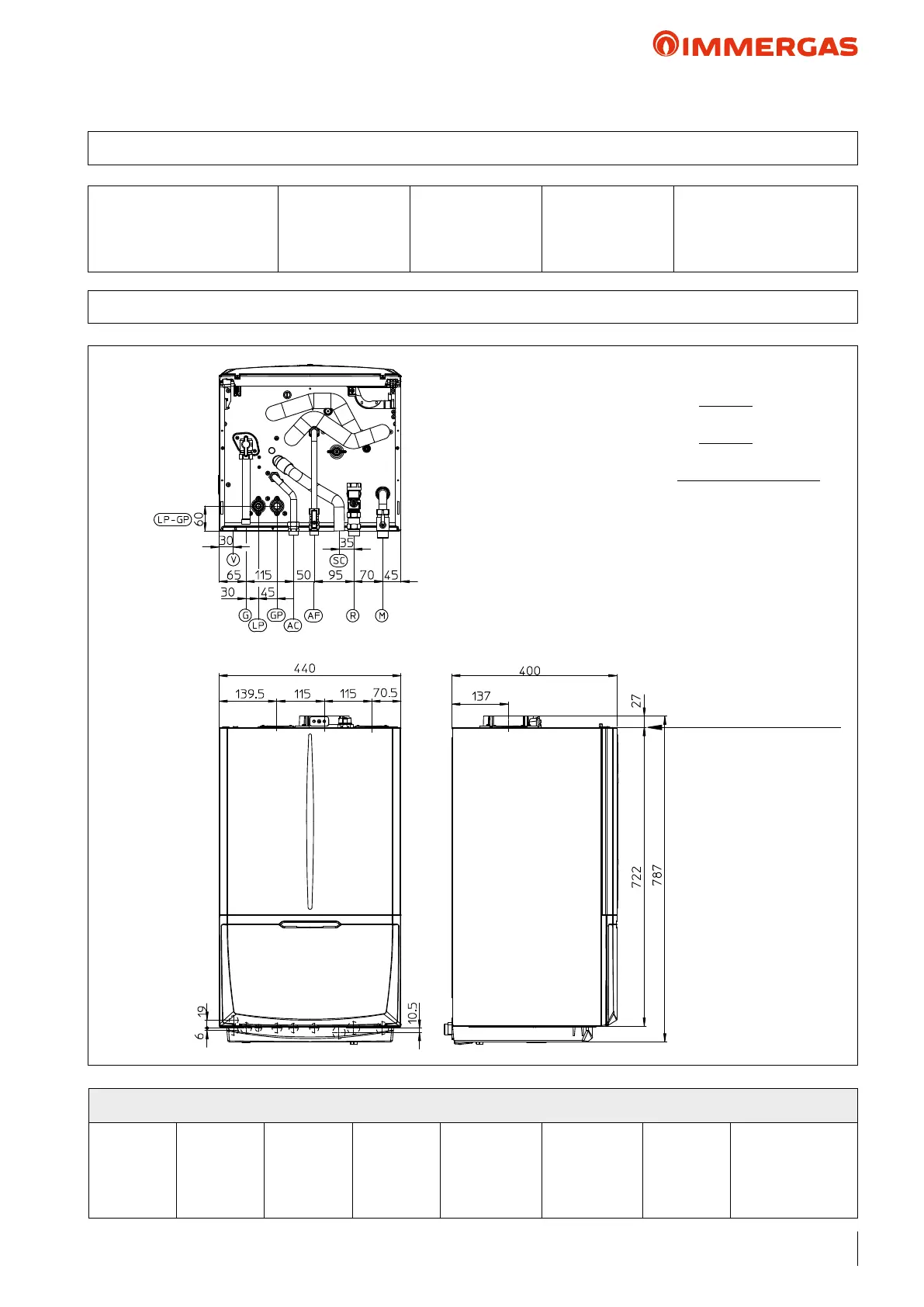
SC = Condensate drain (min. internal Ø= 13 mm)
Distance between casing upper line and
Ø 60/100 concentric bend axis: 105 mm
Distance between casing upper line and
Ø 80/125 concentric bend axis: 215 mm
Distance between casing upper line and
separator bend axis Ø 80/80: A/S = 145; mm A = 115
A/S = intake/exhaust
A = intake
Model
MAGIS COMBO V2
Height mm
787
Width mm
440
Depth mm
400
Ø intake/exhaust mm
100/60 - 125/80 - 80/80
MAGIS COMBO V2
Flow
System
M
3/4"
Return
system
R
3/4"
Inlet
Cold
AF
1/2"
Hot Outlet
AC
1/2"
R32
LP
1/4”
(6.35 mm)
R32
GP
5/8"
(15.88 mm)
Gas
G
3/4"
Expansion vessel
Litres
10 (real 8.3)
3.1 MAGIS COMBO V2 CONNECTIONS
3 MAGIS COMBO V2 MAIN DIMENSIONS