MAGIS COMBO V2
18
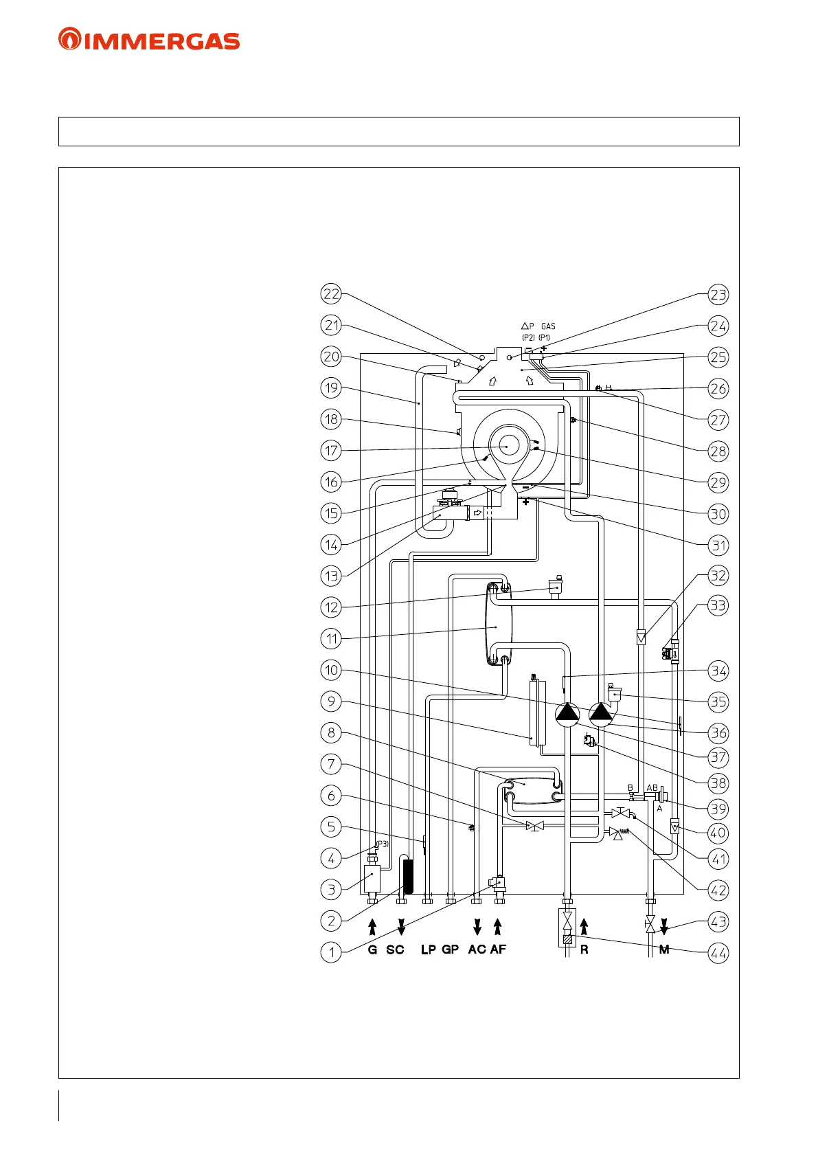
KEY:
1 - D.H.W. ow switch
2 - Condensate drain trap
3 - Gas valve
4 - Gas valve outlet pressure point (P3)
5 - Liquid phase detection probe
6 - DHW probe
7 - System lling valve
8 - DHW heat exchanger
9 - System expansion vessel
10 - Heat pump ow probe
11 - Water - gas plate exchanger
12 - Air vent valve
13 - Fan
14 - Air/gas Venturi manifold
15 - Gas nozzle
16 - Detection electrode
17 - Burner
18 - Flue safety thermostat
19 - Air intake pipe
20 - Manual air vent valve
21 - Heat exchanger safety thermofuse
22 - Air sample point
23 - Flue sample point
24 - ∆P gas pressure point
25 - Fumes hood
26 - Safety thermostat
27 - Heat generator ow probe
28 - Heat generator return probe
29 - Ignition electrodes
30 - Venturi negative signal (P2)
31 - Venturi positive signal (P1)
32 - One-way valve
33 - System ow-meter
34 - Heat pump return probe
35 - Air vent valve
36 - Heat generator circuit circulator
37 - Heat pump circuit circulator
38 - System pressure switch
39 - Motorised 3-way valve
40 - One-way valve
41 - System draining cock
42 - 3 bar safety valve
43 - System interception cock
44 - System interception cock
with inspectable lter
G - Gas supply
SC - Condensate drain
LP - Chiller line - liquid phase
GP - Chiller line - gaseous phase
AC - Domestic hot water outlet
AF - Domestic hot water inlet
R - System return
M - System ow
13 HYDRAULIC DIAGRAM MAGIS COMBO V2 INDOOR UNIT