46
INSTALLERUSERMAINTENANCE TECHNICIANTECHNICAL DATA
1.30 UPM4 CIRCULATION PUMP
e appliances are supplied with a variable speed circulator pump.
During central heating mode, the Auto and Fixed operating modes are available.
- Auto (A5 = 0): automatic circulator pump speed and proportional head: the circulator pump speed varies according to the power sup-
plied by the burner, the greater the power the greater the speed. Moreover, within the parameter, one can also adjust the circulator
pump operating range by setting the maximum speed “A3” parameter (adjustable from 6 to 9) and the “A4” minimum speed parameter
(adjustable from 6 to max set speed).
- ∆T Constant (A5 = 5 ÷ 25 K): the pump speed varies to maintain the ∆T constant between the system ow and return according to set
value K (A5 = 15 Default).
- Fixed (6 ÷ 9): by setting parameters “A3” and “A4” at the same value, the pump operates at constant speed.
For the appliance to work properly, it is not allowed to drop below the minimum speed value.
In domestic hot water mode, the circulator pump always runs at full speed.
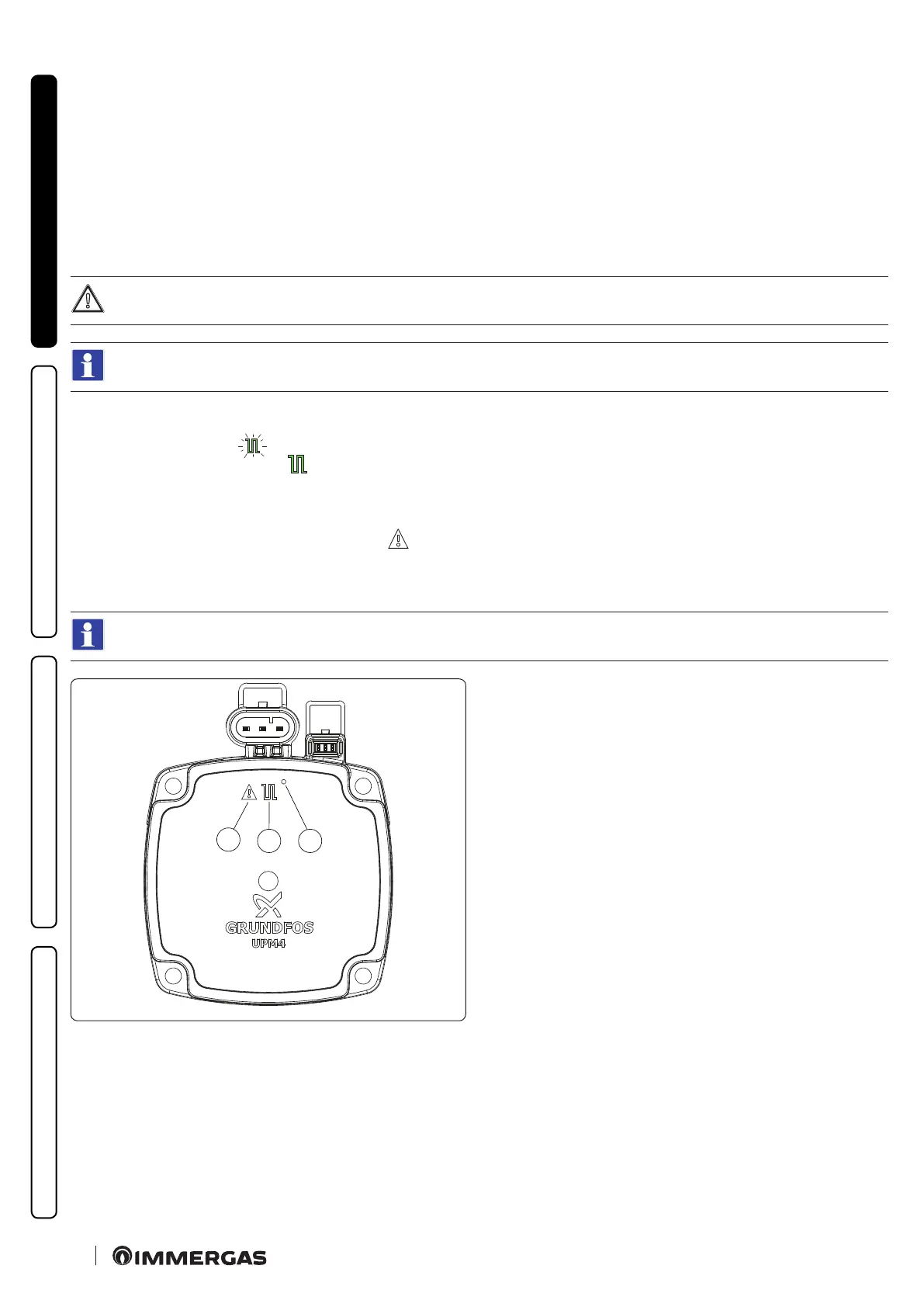
Pump symbols (Fig. ).35):
e symbol 2 ashes green (
) when the pump is powered and the pwm control signal is on (pump ON).
e symbol 2 stays on steady green ( ) when the pump is powered and the pwm control signal is o (pump in Stand-by). In this condi-
tion is it necessary to distinguish between two cases:
- the boiler electronics are not requesting pump ignition => condition OK;
- the boiler electronics are requesting the pump ignition => faulty condition (probable disconnection of the pwm signal).
If the pump detects an alarm, symbol 1 lights up red ( ). is can mean that there is one of the following faults:
- Low power supply voltage.
- Rotor seized (Cautiously turn the screw in the centre of the head to manually release the motor sha).
- Electrical error.
ese anomalies will be signalled on the boiler display as errors “E60” or “E61”.
2
1
3
35
Key (Fig. 35):
1 - Alarm signal (Red)
2 - Functioning status signal (Steady green/Flashing green)
3 - Led (Not used on this model)
Pump release.
If aer a long period of inactivity, the circulator is blocked, adjust the screw in the centre of the head in order to manually release the mo-
tor sha.
Take great care during this operation to avoid damage to the motor.