64
INSTALLER
USERMAINTENANCE TECHNICIAN
TECHNICAL DATA
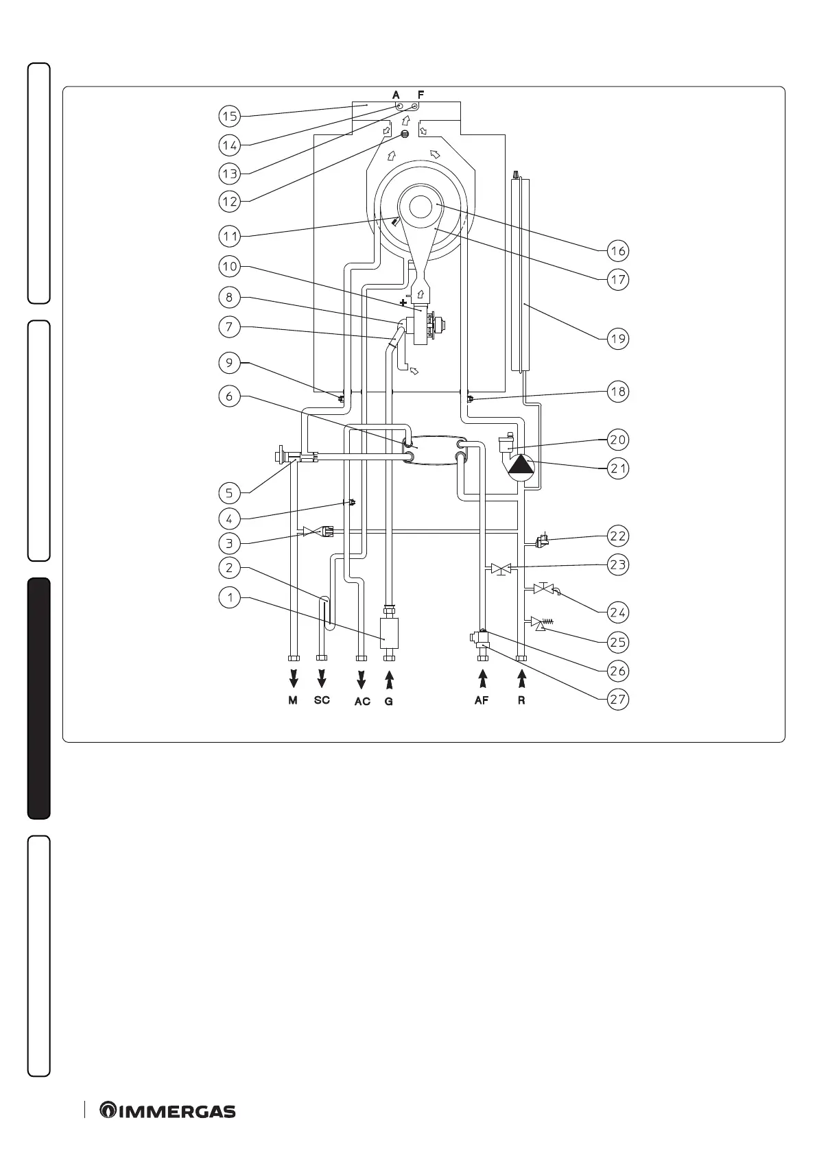
3.4 HYDRAULIC DIAGRAM
39
Key (Fig. 39):
1 - Gas valve
2 - Condensate drain trap
3 - By-pass
4 - D.H.W. probe
5 - 3-way valve (motorised)
6 - D.H.W. heat exchanger
7 - Gas nozzle
8 - Air / gas mixer
9 - Flow probe
10 - Fan
11 - Ignition/detection electrode
12 - Flue probe
13 - Flue sample point
14 - Air sample point
15 - Flue hood
16 - Burner
17 - Air / gas manifold
18 - Return probe
19 - System expansion vessel
20 - Air vent valve
21 - Boiler circulating pump
22 - System pressure switch
23 - System lling cock
24 - System draining cock
25 - 3 bar safety valve
26 - Flow limiter
27 - D.H.W. ow switch
G - Gas supply
AC - Domestic hot water outlet
AF - Domestic hot water inlet
SC - Condensate drain
M - System ow
R - System return