28
INSTALLERUSERMAINTENANCE TECHNICIANTECHNICAL DATA
1.14 OUTDOOR INSTALLATION IN PARTIALLY PROTECTED AREA
By partially protected area, we mean one in which the unit is not directly exposed to the elements (rain, snow, hail, etc.).
If the appliance is installed in a place where the ambient temperature drops below -5°C, use the optional antifreeze kit, checking
the ambient operating temperature range shown in the technical data table in this instruction booklet.
Conguration type B, open chamber and fan assisted (B
23
or B
53
).
Using the relevant cover kit, direct air intake is possible and ue gas is exhausted into a single ue or directly to the outside. In this cong-
uration it is possible to install the appliance in a partially protected place. In this conguration the appliance is classied as type B.
With this conguration:
- air intake takes place directly from the environment in which the appliance is installed (external);
- the ue gas exhaust must be connected to its own single chimney (B
23
) or ducted directly outside via a vertical terminal for direct ex-
haust (B
53
) or via an Immergas ducting system (B
53
).
e technical regulations in force must be respected.
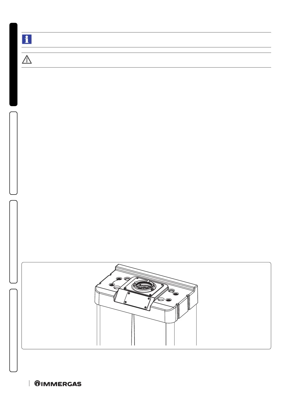
Cover kit assembly (Fig. 15).
Remove the two plugs and the gaskets present from the two lateral holes with respect to the central one. Now cover the le intake hole us-
ing the relevant plate, xing it onto the right side using the 2 previously-removed screws.
Install the Ø 80 outlet ange on the central hole of the boiler, taking care to insert the gasket supplied with the kit and tighten by means of
the screws provided.
Install the upper cover, xing it using the 4 screws present in the kit, positioning the relevant gaskets.
Engage the 90° Ø 80 bend with the male end (smooth) in the female end (with lip seal) of the Ø 80 ange unit to the end stop. Introduce the
gasket, making it run along the bend. Fix it using the metal sheet plate and tighten by means of the clips present in the kit, making sure to
block the 4 gasket aps.
Fit the male end (smooth) of the exhaust pipe into the female end of the 90° Ø 80 bend, making sure that the relevant wall sealing plate is
already tted; this will ensure hold and joining of the elements making up the kit.
Max. length of exhaust duct.
e ue pipe (both vertical or horizontal) can be extended to a max. length of 30 linear metres.
Coupling of extension pipes.
To install push-tting extensions with other elements of the ue, proceed as follows: Couple the pipe or elbow with the male side (smooth)
in the female side (with lip seal) to the end stop on the previously installed element. is will ensure sealing eciency of the coupling.
Conguration without cover kit in a partially protected location (type C appliance).
By leaving the side plugs tted it is possible to install the appliance externally without the cover kit.
Installation takes place using the Ø 60/100 and Ø 80/125 concentric intake/ exhaust kits. Refer to the paragraph on indoor installation.
In this conguration the top cover kit that guarantees additional protection for the appliance is recommended but not compulsory.
e Ø 80/80 separating device cannot be used in this conguration (coupled with the cover kit).
13