89
INSTALLER
USERMAINTENANCE TECHNICIAN
TECHNICAL DATA
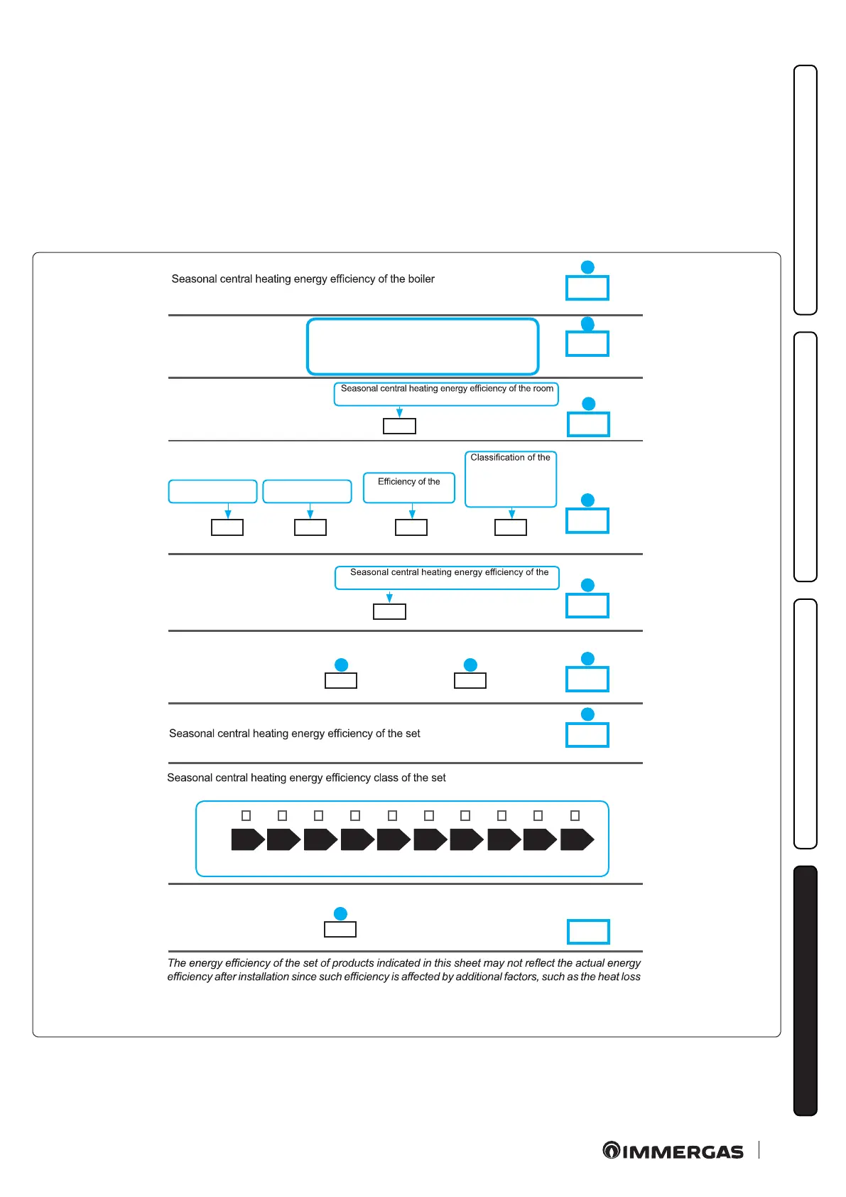
4.7 PARAMETERS FOR FILLING IN THE PACKAGE FICHE
If you wish to install an assembly, starting from this appliance, use the assembly charts in Fig. 68 and 70).
To complete it properly, ll the relevant spaces (as shown in the package che facsimile (Fig. 67 and 69) the values set out in tables “Pa-
rameters for compiling the che” and “Parameters for compiling the DHW package che”.
e remaining values must be obtained from the technical data sheets of the products used to make up the assembly (e.g. solar devices,
integration heat pumps, temperature controllers).
Use board (Fig. 68) for “assemblies” related to the central heating mode (e.g.: boiler + temperature controller).
Use board (Fig. 70)for “assemblies” related to the domestic hot water function (e.g.: boiler + solar thermal system).
Facsimile for lling in the package che for room central heating systems.
Boiler and supplementary heat pump installed with low temperature heat emitters
at 35 °C?
FFrom the board of the heat
pump
%
Temperature control
From temperature
control board
Supplementary boiler
From boiler board
Supplementary heat pump
From the heat pump
board
Solar contribution and supplementary heat pump
Select the lowest
value
in the distribution system and the size of the products compared to the size and features of the building.
Solar contribution
From the board of the solar device
Class I = 1 %, Class II = 2 %,
Class III = 1.5 %, Class IV = 2 %,
Class V = 3 %, Class VI = 4 %,
Class VII = 3.5 %, Class VIII = 5 %
%
+
%
±
(%)
( - ‘I’ ) x 0.1 =
( - ‘I’ ) x ‘II’ =
0.5 x O 0.5 x =
+ ( 50 x ‘II’ ) =
%
%
%
%
+
+
-
Dimensions of the
manifold (in m
2
)
Volume of the
tank (in m
3
)
manifold (in %)
tank
A* = 0.95, A = 0.91,
B = 0.86, C = 0.83,
D-G = 0.81
( ‘III’ x + ‘IV’ x ) x (0.9 x ( / 100) x =
room (%)
< 30 % ≥ 30 % ≥ 34 % ≥ 36 % ≥ 75 % ≥ 82 % ≥ 90 % ≥ 98 % ≥ 125 %≥ 150 %
%
‘I’
+++
++
+
1
2
3
4
5
6
7
4 5
7
67