INDUSTRIAL INDEXING SYSTEMS, INC. IB-11B012
MOTION CONTROL SYSTEM, MSC-250 USER'S GUIDE
MARCH 2003 DESCRIPTION 1 - 11
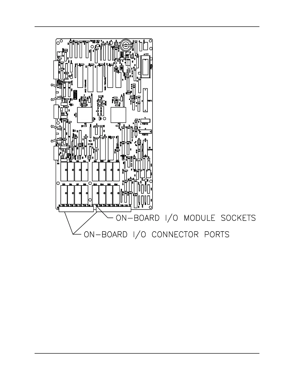
Figure 1.6 - Input/Output Module Locations
controller will change the state of the module at the location, as directed by the
Macroprogram. Monitoring of each of the module locations is supplied by a status indicator
on the front of the controller (refer to "Section 1.3 - Components).
In addition to I/O functions, one of the sixteen position groups ⎯ either the controller board
or one of the I/O expanders ⎯ can be used for programmable limit switches (PLS). These
limit switches can be actuated at master angle bus positions specified by the
Macroprogram. (Refer to the IOE-850 I/O Expander Instruction Manual for additional
information on use of these modules for I/O module and PLS functions.)
 Loading...