IB-11B012 INDUSTRIAL INDEXING SYSTEMS, INC.
USER'S GUIDE MOTION CONTROL SYSTEM, MSC-250
1 - 18 DESCRIPTION MARCH 2003
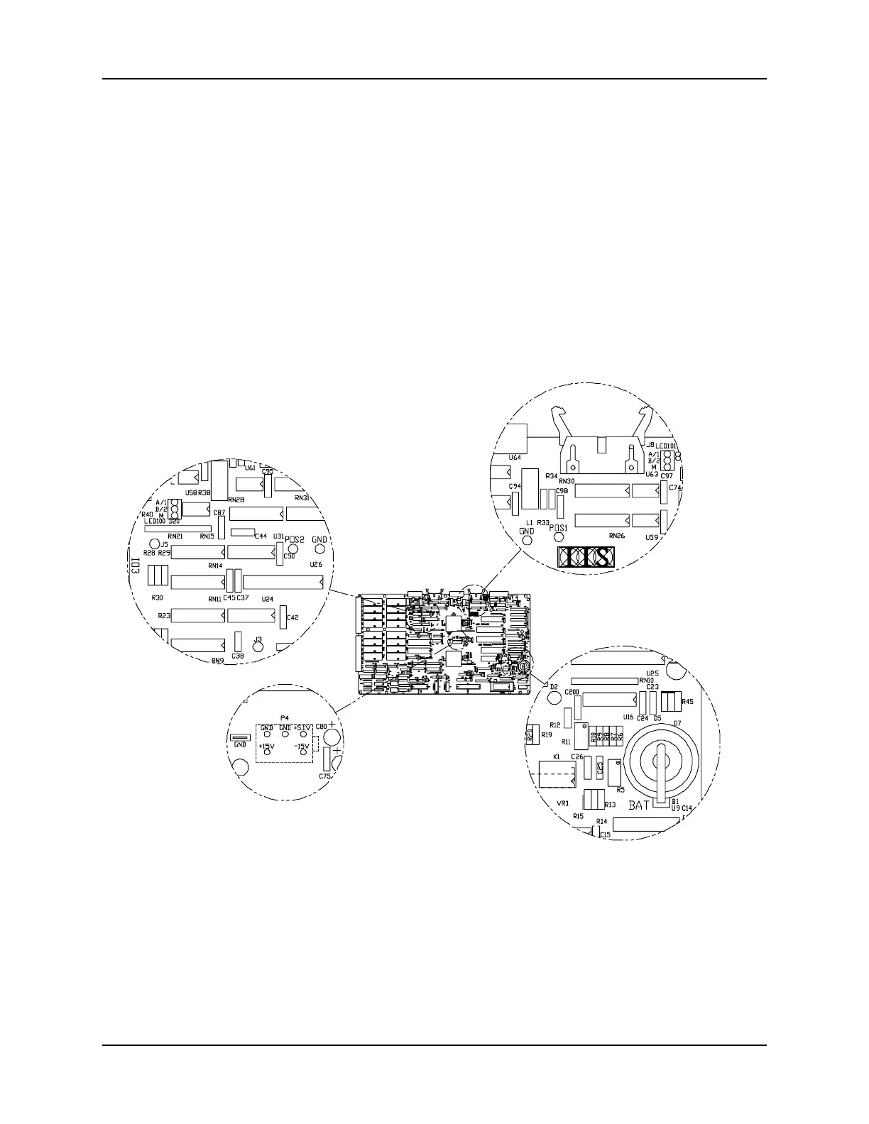
1.3.4 TEST POINTS AND LED INDICATORS
There are a variety of test points and LED indicators on the MSC-250 circuit board which
are used for diagnostic and trouble-shooting purposes (refer to Figure 1.9). Procedures
for use of these items are discussed in "Section 4 - Maintenance".
1. POS and GND Test Points: There is one set of test points for each axis (refer to
Figure 1.10 and Figure 1.11). Place a meter between these
test points to measure the POS OUT signal of the axis. (Refer
to "Section 4 - Maintenance" for applications involving the use
of these test points.)
Figure 1.9 - Circuit Board Test Points
 Loading...