INDUSTRIAL INDEXING SYSTEMS, INC. IB-11B012
MOTION CONTROL SYSTEM, MSC-250 USER'S GUIDE
AUGUST 1998 INSTALLATION 2 - 5
the use of resistors, diodes, and suppressors. These must be supplied by the customer.
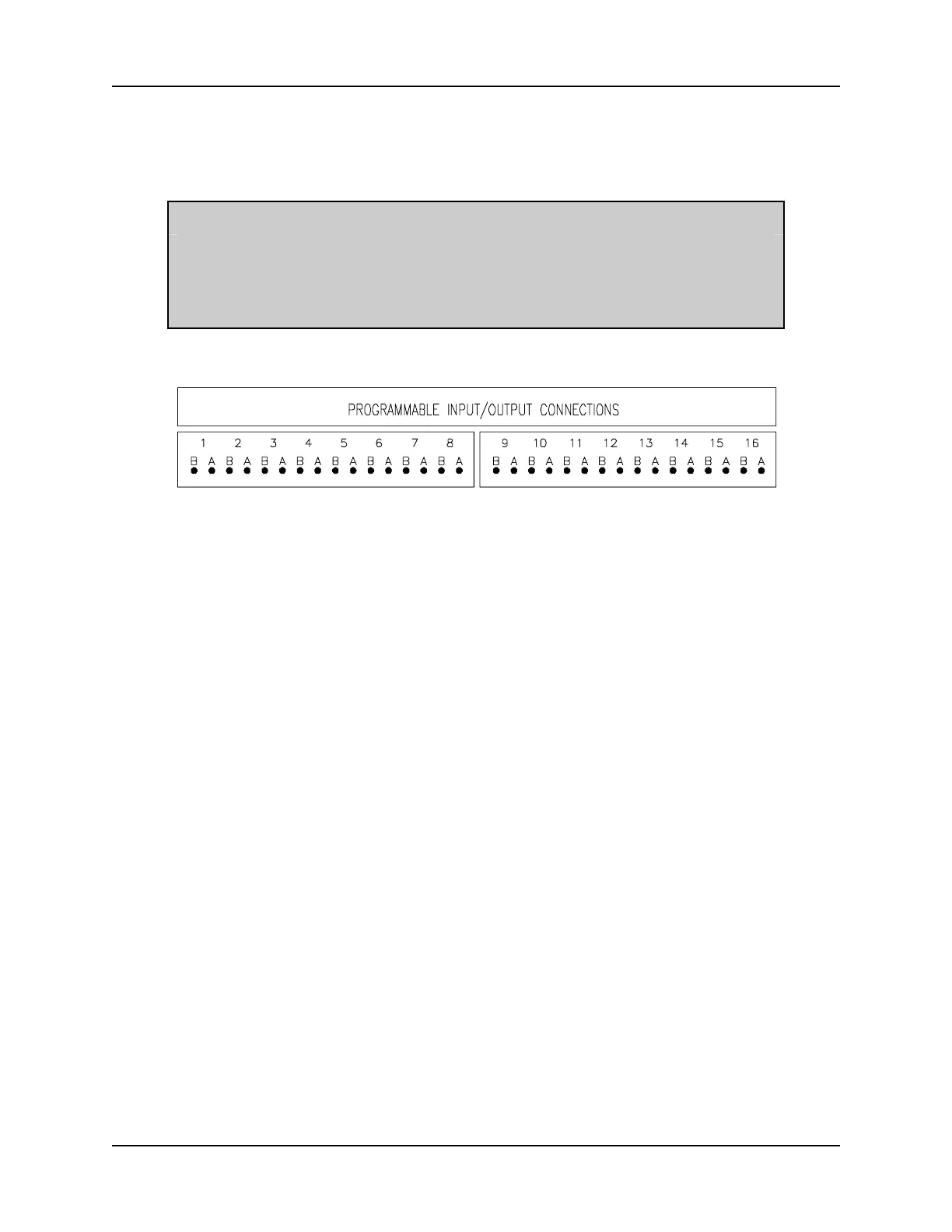
An illustration on the bottom of the MSC-250 front panel shows the appropriate connection
points for the "A" and "B" terminals of each I/O module location (refer to Figure 2.3).
NOTE
The sixteen module locations on the controller or either IOE-850 I/O
Expander may also be used as programmable limit switches. Refer
to the IOE-850 I/O Expander Instruction Manual and Macroprogram
Development System Instruction Book for additional information.
Figure 2.3 - Programmable Input/Output Connections Label
1. Insert the appropriate input or output module in each assigned I/O module
location.
2. If using one or two IOE-850 I/O Expanders, attach the appropriate cables to
daisy-chain the modules to the MSC-250 controller and to each other.
3. Make the proper system connections between the input and output devices and
the "A" and "B" connector locations for each I/O module location.
2.2.2 SYSTEM INTERCONNECTIONS
The system connections for the MSC-250 servo controller will also depend on system
design. Figure 2.4 shows typical system interconnections for the controller, drives, and
encoders. Axis 1 connections are shown with the optional INT-810 interface module. This
module has ribbon cable inputs to match the connectors on the MSC-250 and terminal
outputs to facilitate customer wiring. Axis 2 connections are shown without the interface
module. Such a connection would run direct cables as illustrated.
The pinouts for the encoder cable connector and drive cable connector are shown in
Figure 2.4. These are repeated in the sequence of pinout illustrations which follow along
with the pinouts for the communication ports. The balance of these instructions assume all
ports and connectors are used although this may not be the actual case.
 Loading...