INDUSTRIAL INDEXING SYSTEMS, INC. IB-11B012
MOTION CONTROL SYSTEM, MSC-250 USER'S GUIDE
AUGUST 1998 INSTALLATION 2 - 7
1. For each axis, connect the encoder
to the controller.
a. Connect the encoder end of
cable C-303yyy to the
encoder. Make sure the
connector is securely seated.
b. Connect the other end of
cable C-303yyy to the
encoder cable connector on
the MSC-250 controller.
Make sure the connector is
securely seated.
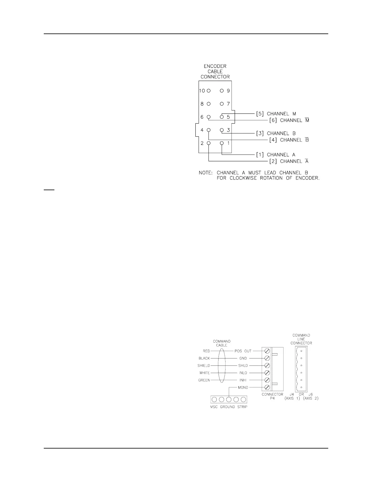
Figure 2.5
Encoder Cable Connector Pinouts
OR
a. If the INT-810 interface is used, connect the encoder end of cable C-300yyy
to the encoder. Make sure the connector is securely seated.
b. Connect each wire of cable C-300yyy to the correct terminal of the INT-810
interface module (refer to Figure 2.4) and plug the encoder connector from
the INT-810 into the encoder cable connector on the MSC-250 controller.
Make sure all wires terminals are tight and that the connector is securely
seated.
2. For each axis, connect the drive to the controller.
a. Connect the drive end of the
command cable to the drive.
Make sure the connector is
securely seated.
b. Connect the other end of the
command cable to the
command line connector on
the MSC-250 controller. Make
sure the connector is securely
seated.
Figure 2.6
Command Line Connector Pinouts
 Loading...