IB-11B012 INDUSTRIAL INDEXING SYSTEMS, INC.
USER'S GUIDE MOTION CONTROL SYSTEM, MSC-250
2 - 8 INSTALLATION AUGUST 1998
3. If using the INT-810 interface module, connect the 5 VDC power supply to the
proper terminals on the interface module (refer to Figure 2.4).
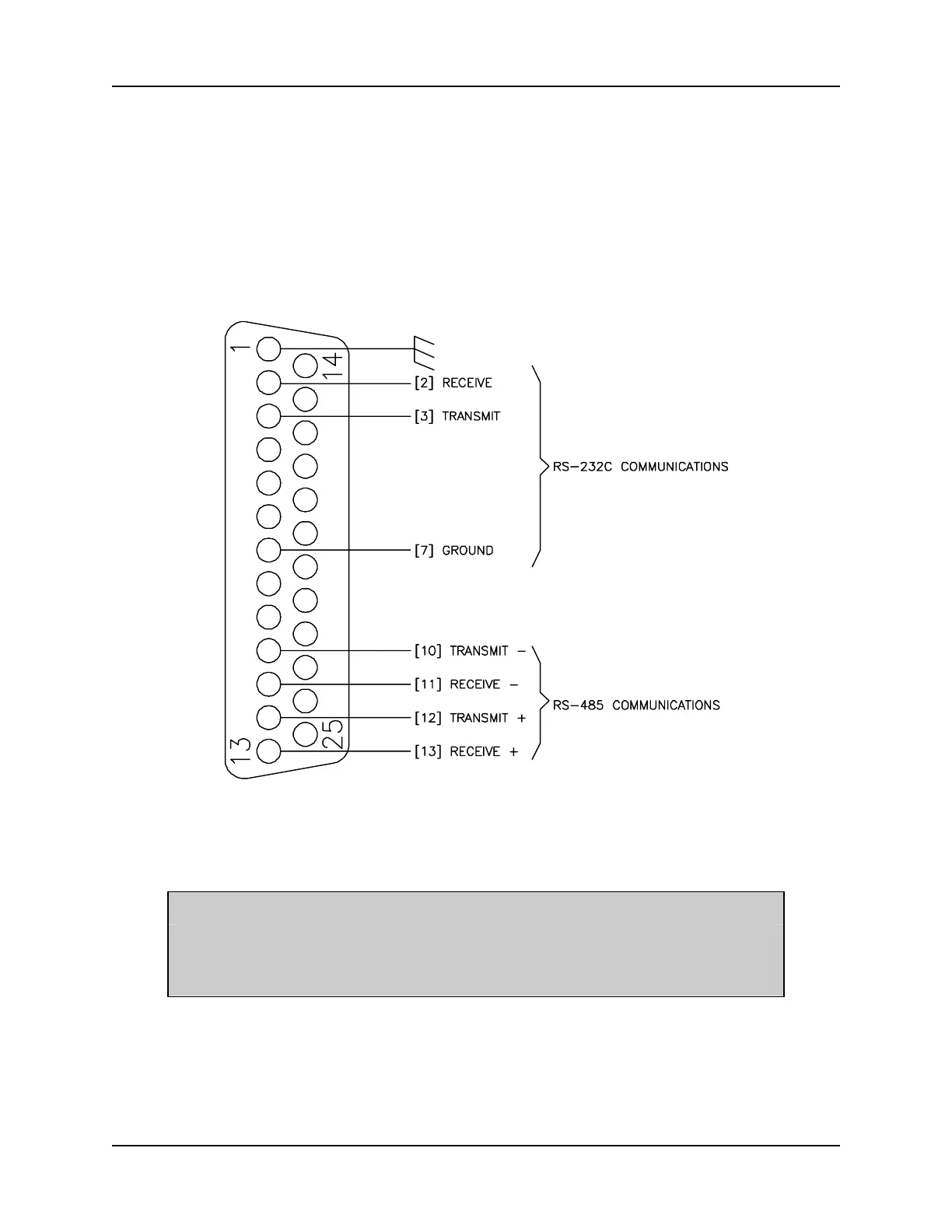
4. Connect the communications cables from PORT 1, PORT 2, and PORT 3 to their
respective communication devices. Refer to the pinouts shown in Figure 2.7,
Figure 2.8, and Figure 2.9, respectively.
Figure 2.7 - PORT 1 Pinouts
NOTE
The last device in an RS-485 multidrop communications chain must
have a 120 ohm, 1/4 watt terminating resistor connected between
"Receieve -" and "Receive +".
 Loading...