IB-11B012 INDUSTRIAL INDEXING SYSTEMS, INC.
USER'S GUIDE MOTION CONTROL SYSTEM, MSC-250
1 - 20 DESCRIPTION MARCH 2003
3. Position-error Output Signal: One test point for measuring the following error is
provided for each axis (refer to Figure 1.11). J3 is the test
point for axis 1 and J5 is the test point for axis 2. (Refer to
"Section 4 - Maintenance" for applications involving the use of
these test points.)
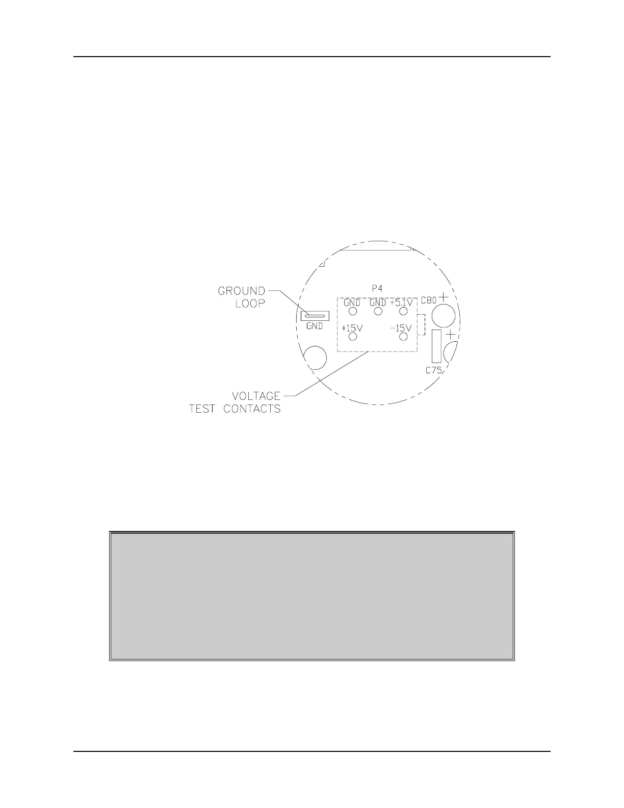
4. Voltage Test Points: The voltage test point block and additional ground loop are
available for checking the system voltages used by the
controller (refer to Figure 1.12).
Figure 1.12 - Voltage Test Contacts
5. Low Input Line Power Indicator: LED indicator D2 will illuminate whenever input
line power is reduced to a point that could result in improper
controller operation. The status indicator on the cover of the
controller will also display an error code.
CAUTION
THE TWO POTENTIOMETERS INDICATED IN FIGURE 1.13 CONTROL
USE OF BATTERY POWER TO PROTECT THE NON-VOLATILE
MEMORY REQUIRED TO MAINTAIN THE OPERATING PROGRAM IN
THE CONTROLLER. THESE POTENTIOMETERS ARE FACTORY SET
AND MUST NOT BE ADJUSTED. IMPROPER ADJUSTMENT OF
THESE POTENTIOMETERS COULD RESULT IN LOSS OF PROGRAM
MEMORY.
 Loading...