IB-11B012 INDUSTRIAL INDEXING SYSTEMS, INC.
USER'S GUIDE MOTION CONTROL SYSTEM, MSC-250
4 - 2 MAINTENANCE AUGUST 1998
4. Gently lift the spring clip and replace with a similar type battery. Make sure the
contacts are properly oriented.
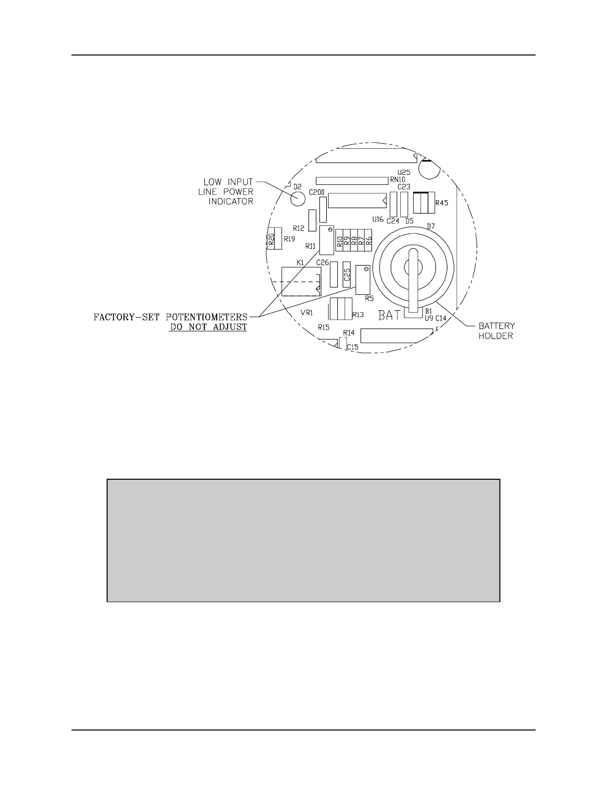
Figure 4.1 - Battery Holder
4.1.2 FIRMWARE REPLACEMENT
1. Each firmware EPROM is located in a 40-pin LIF (Low Insertion-Force) socket on
the controller circuit board (refer to Figure 4.2).
NOTE
When shipped, the EPROM chips will be labeled as SFO5102R_ for
the main firmware or SFO5103R_ for axis software where the "_"
position represents a revision number. Each chip must be replaced
in its proper socket. The main firmware is located in socket U33 and
the axis firmware is located in socket U19 (refer to 1). If the wrong
firmware is in the socket, a fault code will be displayed on the status
LED.
2. Note the location of the #1 pin on the socket as indicated on the old EPROM chip
in the socket.
 Loading...