INDUSTRIAL INDEXING SYSTEMS, INC. IB-11B012
MOTION CONTROL SYSTEM, MSC-250 USER'S GUIDE
AUGUST 1998 INSTALLATION 2 - 9
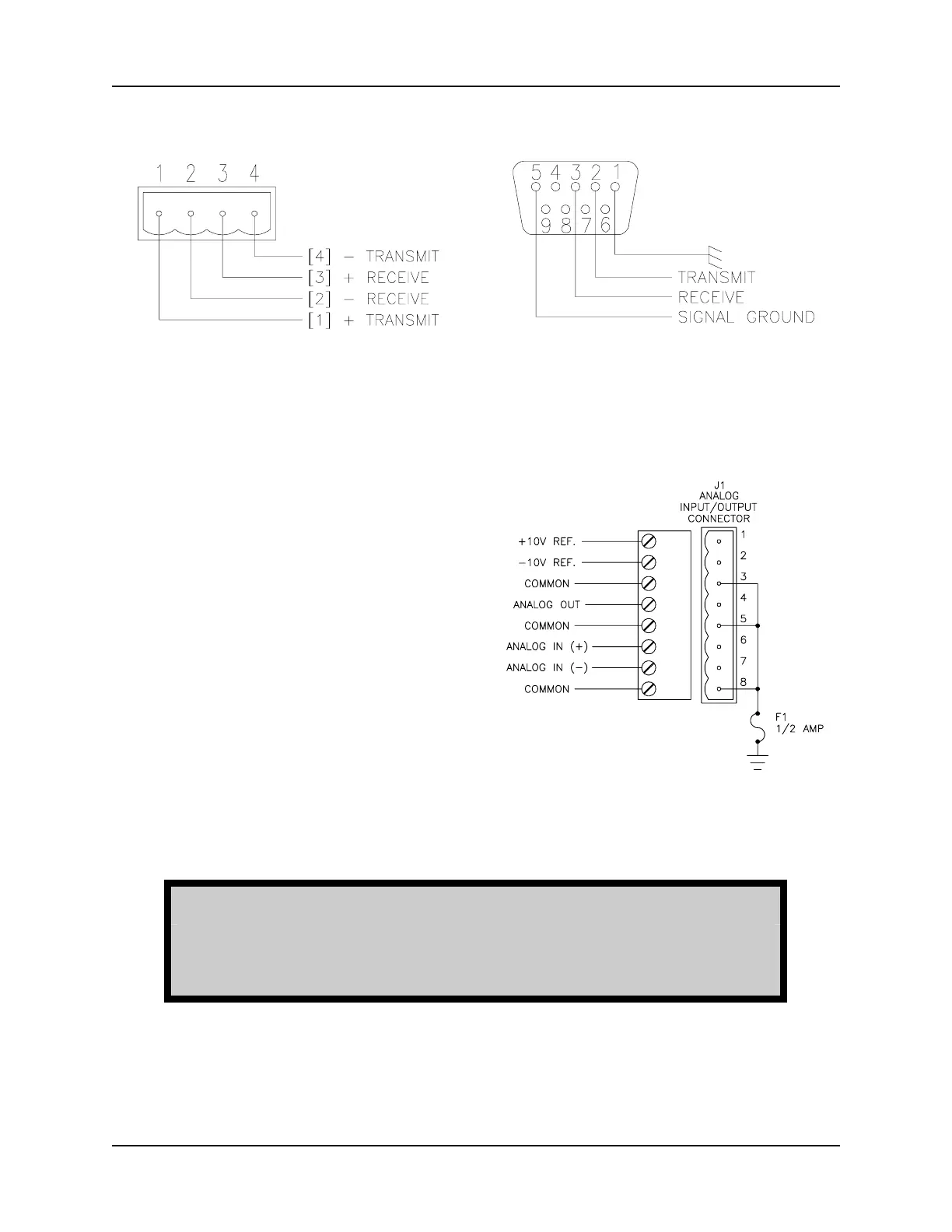
Figure 2.8
PORT 2 Pinouts
Figure 2.9
PORT 3 Pinouts
Figure 2.10
Analog Channel Connections
5. Connect the analog input/output
channels and reference voltages.
a. Connect the controller end of
the cable for the analog input
and output channels to the
analog input/output connector
(refer to Figure 2.10).
b. Connect any analog input, or
analog output to the other
end of the connector cable
(refer to Figure 2.11).
c. If a potentiometer input is to
be used, connect the
potentiometer to the cable as
shown in Figure 2.11.
WARNING
DOUBLE CHECK ALL WIRING CONNECTIONS. MAKE SURE ALL
ARE PROPER AND SECURE. IMPROPER CONNECTIONS COULD
RESULT IN SYSTEM MALFUNCTIONS.
 Loading...