IB-11B012 INDUSTRIAL INDEXING SYSTEMS, INC.
USER'S GUIDE MOTION CONTROL SYSTEM, MSC-250
4 - 6 MAINTENANCE AUGUST 1998
4.2.2 SYSTEM TESTS
The tests in this section are designed to be followed sequentially until the problem is found.
4.2.2.1 Velocity Loop Test
The velocity loop test removes the controller from the loop for the purpose of testing the
motor, drive, and power supply. In this test, the drive is manually enabled and a velocity
command voltage is applied to the amplifiers by means of a Volt Ohm Meter (V.O.M.)
command input.
WARNING
THIS TEST CAUSES THE MOTOR TO TURN. MAKE SURE THAT THE
MECHANICAL LOAD WILL ACCEPT MOVEMENT IN BOTH
DIRECTIONS WITHOUT DAMAGE TO THE EQUIPMENT AND THAT
ALL PERSONNEL ARE CLEAR BEFORE STARTING THIS TEST.
1. Remove controller and system power.
2. Open the controller cover and set the MODE selector switch to position 1. Close
the cover.
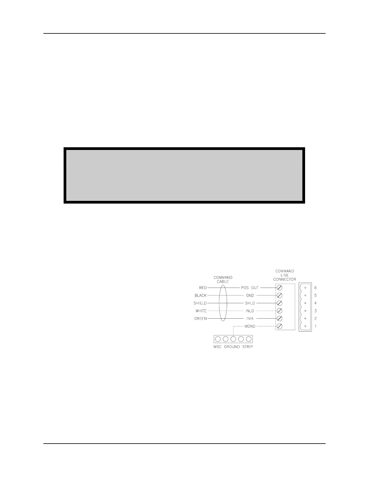
3. Remove the 6-Pin command line
connector, for the axis to be tested,
from the controller (refer to "Section
1.3 - Components").
Figure 4.4
Controller Connectors
4. Restore power to the controller and
system.
5. Using a short jumper wire,
temporarily short together the INLO
(white wire) and INHI (green wire)
terminals on the command line
connector (refer to Figure 4.4).
This step causes the drive
(amplifier) to turn "On" manually.
6. Apply system power. The motor should be stationary and should resist any
attempt to turn the motor shaft.
 Loading...