INDUSTRIAL INDEXING SYSTEMS, INC. IB-11B012
MOTION CONTROL SYSTEM, MSC-250 USER'S GUIDE
MARCH 2003 DESCRIPTION 1 - 19
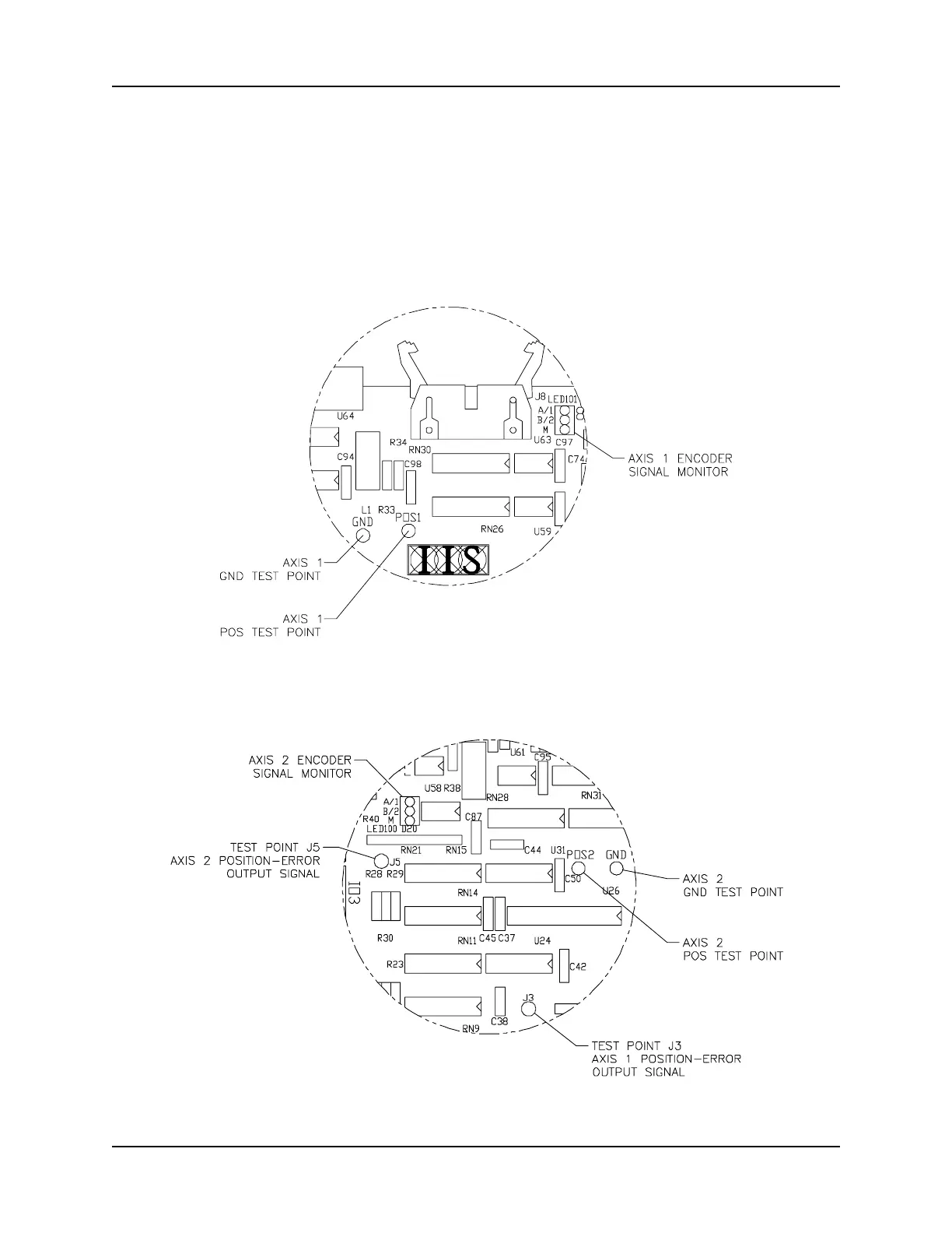
2. Encoder Signal Monitor: There is one set of three LED encoder signal indicators
for each axis (refer to Figure 1.10 and Figure 1.11). One
LED is assigned to each channel of the encoder and
illuminates each time the channel generates a pulse. The
quadrature channels (1 and 2) will flash very rapidly while the
encoder shaft is turning. The indicator for the marker channel
will flash once per encoder-shaft revolution.
Figure 1.10 - Axis 1 Test Points and Indicators
Figure 1.11 - Axis 1 and Axis 2 Test Points and Indicators
 Loading...