INDUSTRIAL INDEXING SYSTEMS, INC. IB-11B012
MOTION CONTROL SYSTEM, MSC-250 USER'S GUIDE
MARCH 2003 DESCRIPTION 1 - 13
1.3 COMPONENTS
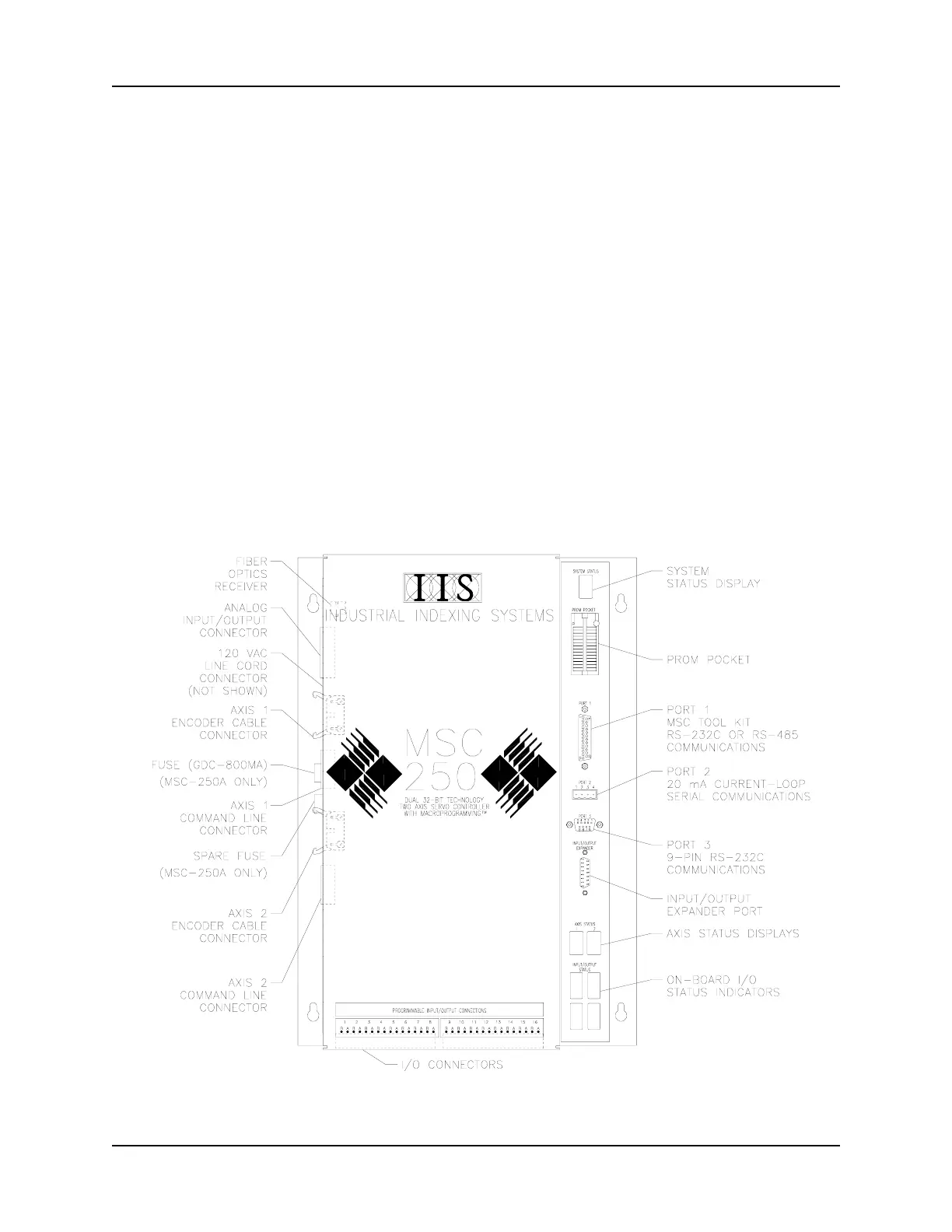
Figure 1.7 shows the various connectors and status indicators of the MSC-250 controller.
Several of the connectors are attached to the printed circuit board of the controller and
protrude through the side or bottom of the controller cabinet. These connectors are shown
as dotted lines to indicate their relative position, even though they are not really visible from
this view.
1.3.1 STATUS INDICATORS
1. SYSTEM STATUS Display: This 7-segment LED (Light Emitting Diode) with
decimal place indicates the status of the main
processor. Each number displayed represents a
specific status code. (Refer to "Section 3.2 -
Controller Use and Status" for the meaning of these
codes.) An illuminated decimal point indicates that the
program is running.
Figure 1.7 - Connectors and Status Indicators
 Loading...