IB-11B012 INDUSTRIAL INDEXING SYSTEMS, INC.
USER'S GUIDE MOTION CONTROL SYSTEM, MSC-250
1 - 16 DESCRIPTION MARCH 2003
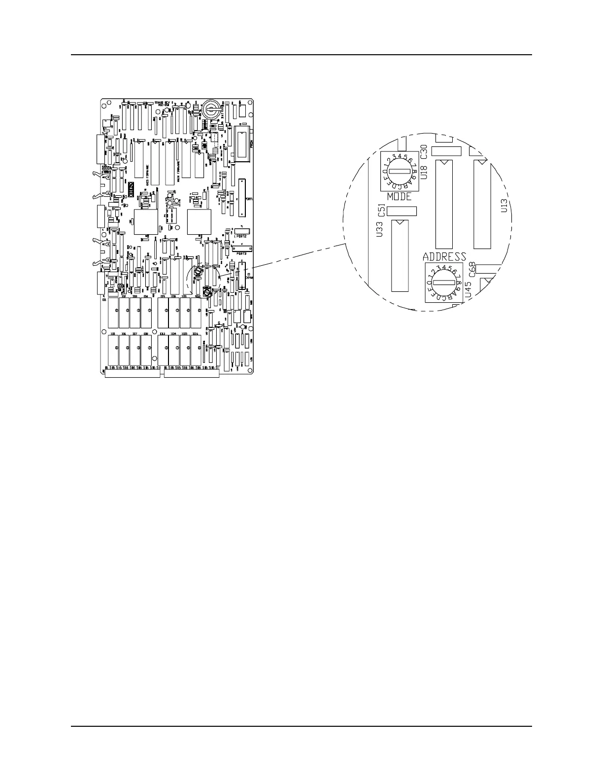
Figure 1.8 - ADDRESS and MODE Selector Switches
1.3.3 SELECTOR SWITCHES
There are two 16-position rotary selector switches on the MSC-250 circuit board as
indicated in Figure 1.8.
1. ADDRESS: This selector switch is used in conjunction with communications
PORT 1. If this switch is in the "0" position, the port will
communicate using the RS-232C serial communications protocol.
Any of the other positions ¾ 1 through F ¾ are used to designate
the node number of the controller when it is used for RS-485 serial
communications.
2. MODE: This selector switch is used to determine the operating mode of the
controller.
Normal Operation = Port 1, 2, & 3 default to 9600 Baud - Packet
Protocol.
 Loading...