INFICON Description | 4
CU1000-Operating-Instructions-jina54en1-09-(2404) 9 / 46
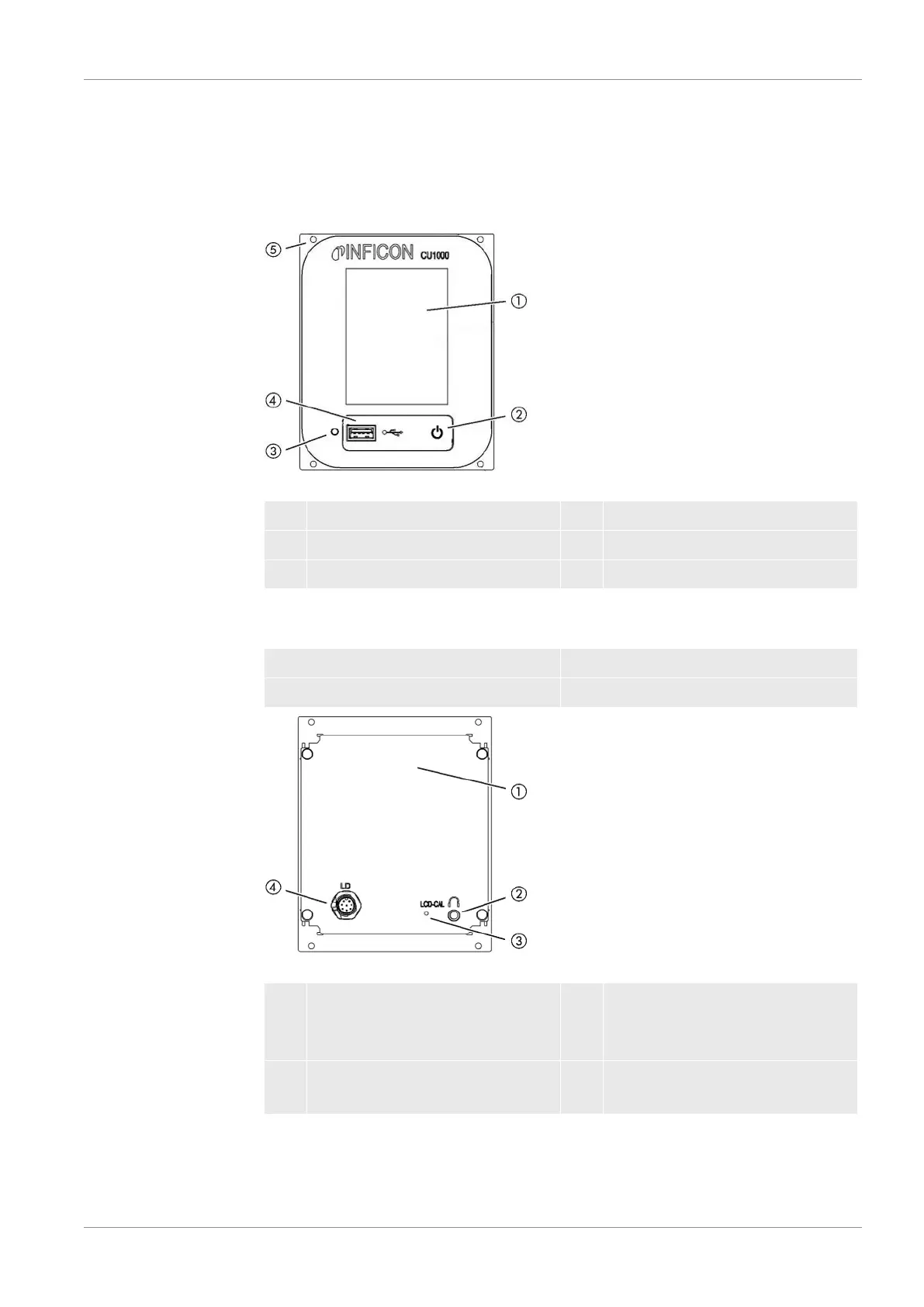
4 Description
4.1 Device setup
Fig.1: Front view
1 Touchscreen 4 USB port
2 Status LED 5 Mounting holes
3 Rest button
Status LED
Status LED illuminated Control unit operates normally
Status LED flashing Display is set to power saving mode
Fig.2: Rear view
1 Rating plate with control unit 3 Calibration button for calibrating
the touch screen (LCD-CAL), can
be operated with touch PIN
2 Connection for headphones 4 Connection for the cable to the
leak detector (LD)