Introduction to Digital Power Conversion
XMC4000/1000 Family
Converter Topologies
Application Guide 19 V1.0, 2015-01
3.3 PFC
Abstract
The Power Factor (PF) is defined as the transfer ratio of real power [Watt] to apparent power [VA]:
PF = Real Power / Apparent Power [Watt / VA]
The Power-Factor-Correction (PFC) purpose is (according to the environmental context) to achieve:
Real Power = Apparent Power
i.e.:
PF = 1
PFC Rectifier
A PFC rectifier accomplishes “PF = 1” by phase correct rectification of the mains AC voltage – so that
the current conduction angle becomes fully 180
o
in both half periods – phase correct to the mains AC
voltage – i.e. without any parasitic or reactive signal components reflected back into the mains lines:
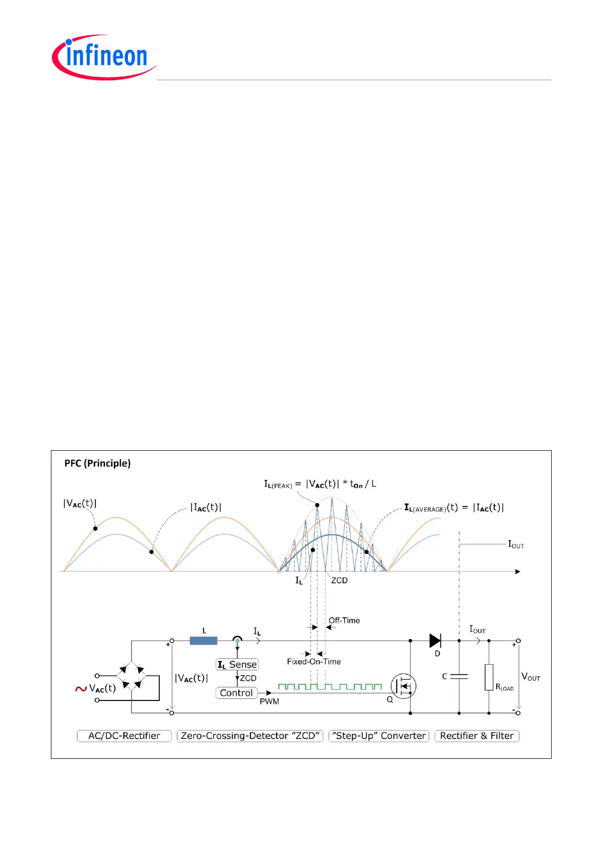
See Figure 7.
In principle, the mains is rectified into a sinusoidal half-wave rippling DC voltage. In turn it is converted
to a ripple-free DC output voltage by a Boost PFC – e.g. by Fixed-On-Time inductor current (I
L
) mode
control. (Each Off-Time interval lasts till the current (I
L
) falls back to Zero-Crossing-Detection, ZCD.)
Since all t
On
pulses are fixed, the I
L(PEAK)
and I
L(AVERAGE)
envelopes will follow the |V
AC
(t)| in proportion.
Figure 7 Boost Power-Factor-Correction (PFC) – E.g. in Fixed On-Time Current Mode Control

 Loading...
