Introduction to Digital Power Conversion
XMC4000/1000 Family
PWM Generation
Application Guide 37 V1.0, 2015-01
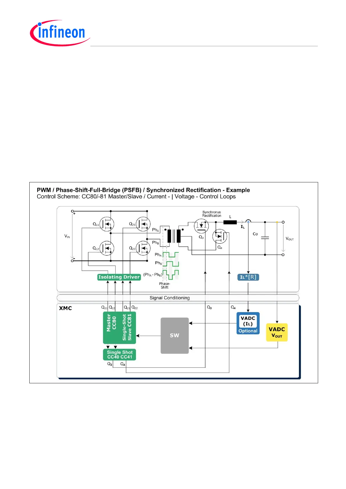
4.11.1 Power Conversion Control Example
The PSFB controller performs DC/DC power conversion in stages:
1. Split the DC input voltage (V
IN
) in to two phase-shifted pulse streams (Ph
A
and Ph
B
), controlled by
a PWM Phase-Shift-Master-Slave configuration with the CCU8 slice pair CC80/-81 (See also
Figure 24).
2. Invoke a transformer, which offers an isolating path for the voltage difference Ph
A
minus Ph
B
, on its
primary coil, over to the next stage, via two complementary secondary coils.
3. A “step-down” converter configuration is used, with synchronous rectification with the switch-pair
(Q
3
, Q
4
), as an efficient replacement for diodes by offering lower voltage drop.
− The switch-pair (Q
3
, Q
4
) rectifies and interleaves the positive levels of the two secondary
voltages from the transformer into a PWM pulse stream. The PWM will get a duty cycle that is
proportional to the phase shift |Ph
A
o
– Ph
B
o
|.
− The inductor (L) and the output capacitor (C
O
) serve as an LP-filter for the output voltage (V
OUT
).
Figure 26 PWM – Variable Phase-Shift Control – Example Using Synchronous Rectification
There is a fast Current Mode Control loop, sensed by a Fast Compare VADC channel, via a stage ‘R’
acting as trans-resistance, and there is a slow Voltage Mode Control loop via another VADC channel.
The MOSFETs require some kind of isolating driver stage (e.g. opto-couplers).

 Loading...
