Introduction to Digital Power Conversion
XMC4000/1000 Family
Modulation
Application Guide 52 V1.0, 2015-01
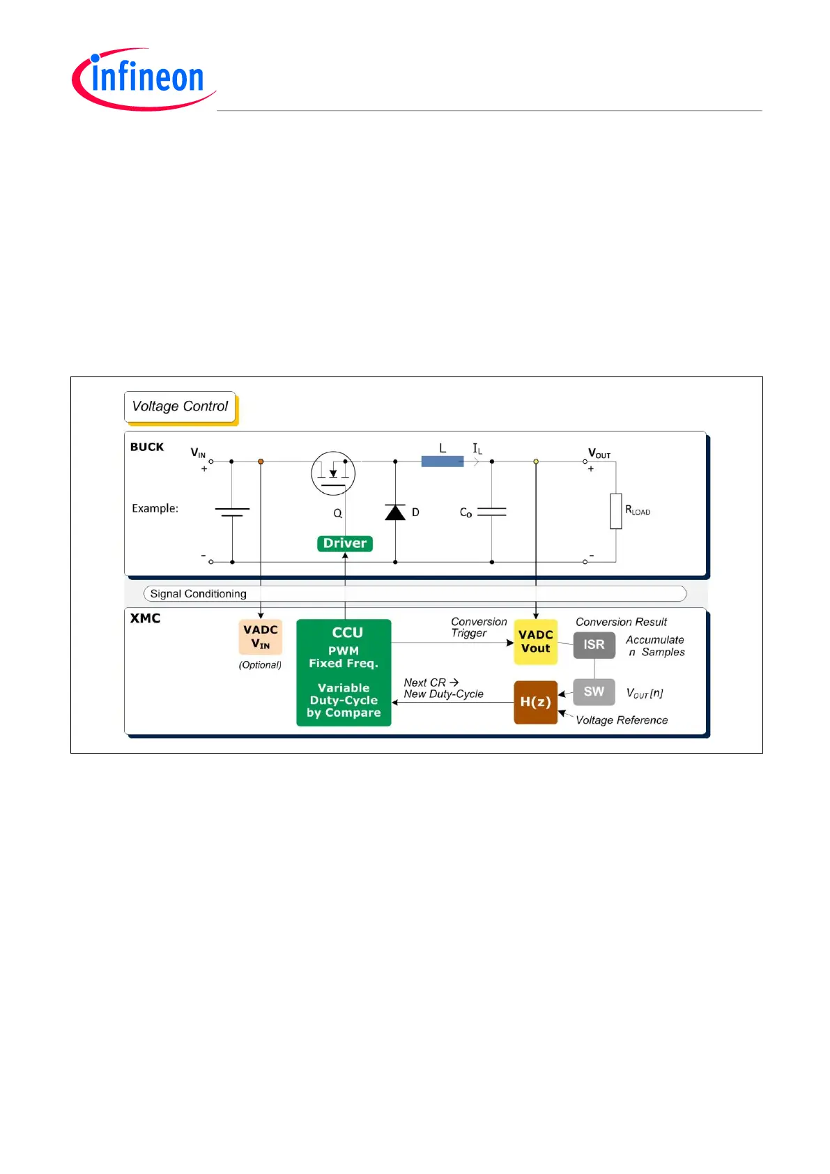
6.1 Voltage Control (VC)
Reference Topology
Buck converter.
Steady State Transfer Function
The steady state duty-cycle-to-output transfer function here is based on V
OUT
=D*V
IN
, maintained by
the variable duty-cycle D (%) of a fixed frequency PWM from a CCU, driving the switch (Q).
The feed-back function of the VC loop modulates D, so that the target output voltage is maintained.
Figure 39 Modulation – Voltage Mode Control – Buck Converter
Steady State DC VC Loop
The long-term average output voltage (V
OUT(n)
) has a fixed target value relative to a voltage reference.
A deviation will be forced towards 0 by the feed-back loop gain, maintained by a New Duty-Cycle via
software. The conversion rate for the n sampling cycles, sensed by the VADC, is triggered by a CCU
timer (See also Figure 40).

 Loading...
