Introduction to Digital Power Conversion
XMC4000/1000 Family
PWM Generation
Application Guide 25 V1.0, 2015-01
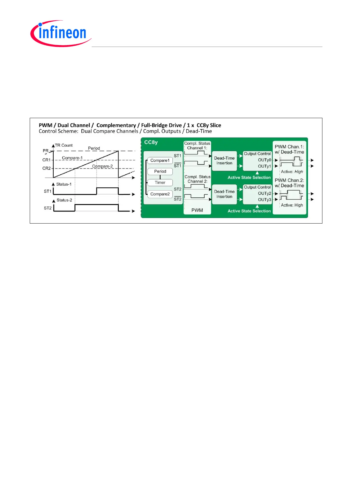
4.3 Dual Channel with Complementary Outputs with Dead-Time, using CCU8
By using both channels (Ch1 and Ch2) in a CC8y timer slice, it is possible to output a dual pair of
complementary PWM signals to target 1 or 2 full-bridges.
Dead-Time insertion of individual rise-/fall times can be provided independently, as well as accurate
output active level settings and trap care.
Figure 14 PWM – Dual Channel Full-Bridge Drive
4.4 Dual Channel with Complementary Outputs with Dead-Time, using CCU4
A ‘sea’ of individual ‘timer-cells’
The timer slices of all CCUs can be regarded as a ‘sea’ of individual ‘timer-cells’ that are
interconnectable to act upon each other’s event requests, and accomplish dedicated and compound
timing functions.
Event sources and function commands are easily mapped by registers: CC4(8)yINS and
CC4(8)yCMC.
A typical example is a CCU4 Full-Bridge drive with complementary outputs and individual Deadtimes
(see Figure 15).
PWM with Complementary Outputs by Using CCU4 Single-Shot Timers
A complementary PWM output pair can be built from two timer slices (e.g. CC40 and CC41) in single-
shot mode. The timers run, one at a time so that when one timer stops after its single-shot, it starts
the other timer with an event request Input Function ‘Start’. This can be mapped via interconnect
settings.
PWM with Dual Complementary Outputs by Using Synchronized Single-Shot Timer Pairs
When adding the other two timer slices of a CCU4 (e.g. CC42 and CC43), Full-Bridge control is
possible. Dead-Time insertion can be added and the ‘channel 1’ and ‘channel 2’ (CC40/41 and
CC42/43) can be synchronized with a Global Start.
PWM with Complementary Outputs Including Dead-Time Insertions
By using a preset compare register to shorten the output width of each single-shot, it is possible to get
individual deadtimes for different switch delays, and enable a Full-Bridge drive capability with a
CCU4.
Note: The pulse width modulating role is performed by period registers – not by compare registers.

 Loading...
