Introduction to Digital Power Conversion
XMC4000/1000 Family
Modulation
Application Guide 56 V1.0, 2015-01
Steady State DC Average Current Mode Control Loop
A long term average output voltage, based on n accumulated samples by the ISR, represents a
proportional value of the average current I
OUT
(Avrg), and has a fixed target value relative to a voltage
reference. Any deviation will be forced towards 0 by the loop gain, maintained by a New Duty-Cycle.
The conversion rate for ‘n’ sampling cycles, sensed by the VAC, is triggered by the CCU8 timer and
determines the time constant of the feedback control in the loop; i.e. the loop might be very slow,
depending on the accuracy requirements.
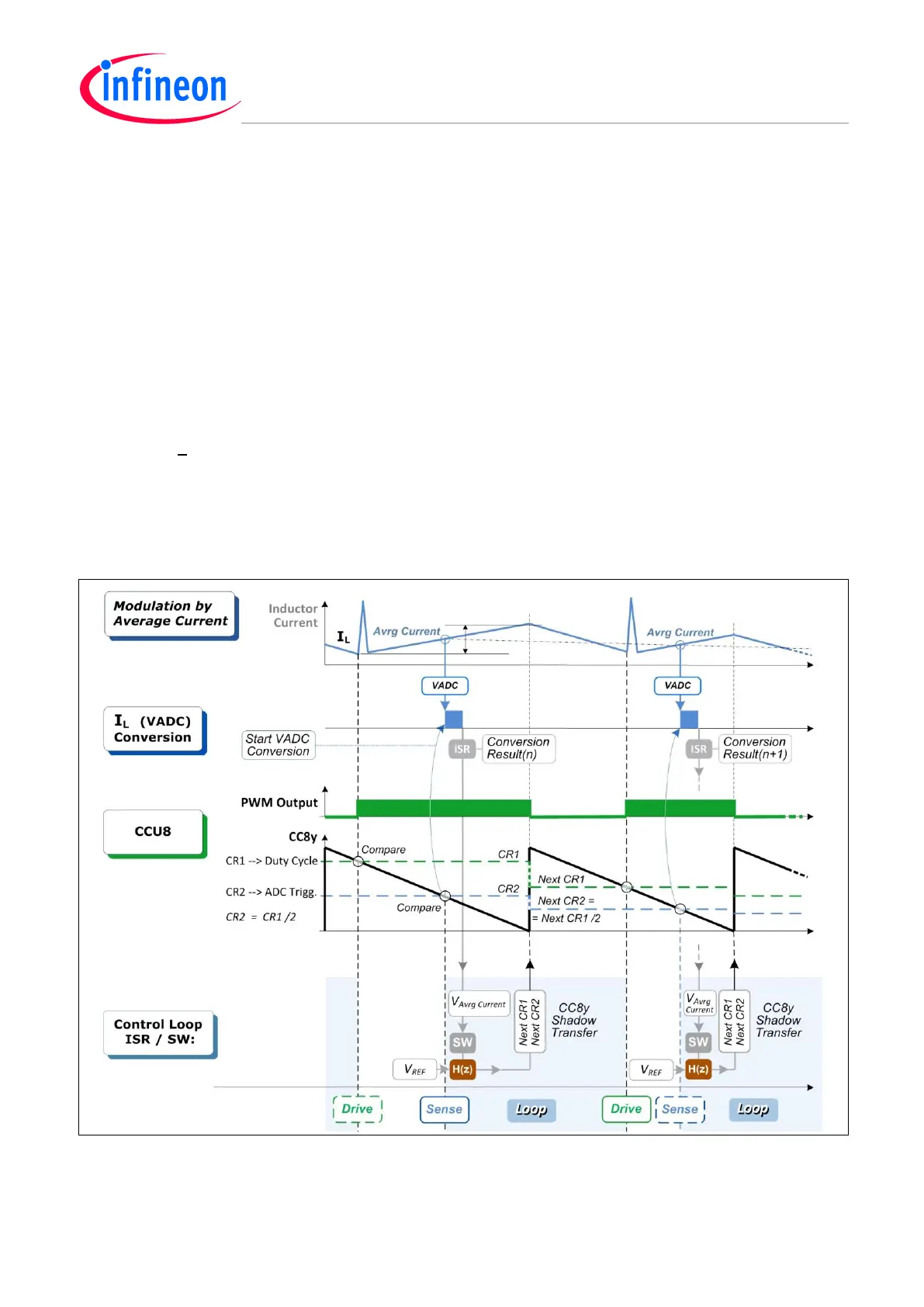
6.2.2 Average Current Control, Edge-Aligned Scheme
Take the following expression:
I
L
= I
OUT
(Avrg) +
∆I
L
This indicates where to sense and sample the average current I
OUT
(Avrg), named as “Avrg Current” in
the Timing Scheme diagram, which describes the inductor current (I
L
) and the PWM Output control of
the switch (Q) commutations. Down-count mode input control is used in this instance.
Note: The output Active State Selection is set output ACTIVE LOW; i.e. it is inverted to the status bit.
Figure 42 Average Current Mode Control (ACC) – Edge Aligned Timing Scheme

 Loading...
