Introduction to Digital Power Conversion
XMC4000/1000 Family
Modulation
Application Guide 62 V1.0, 2015-01
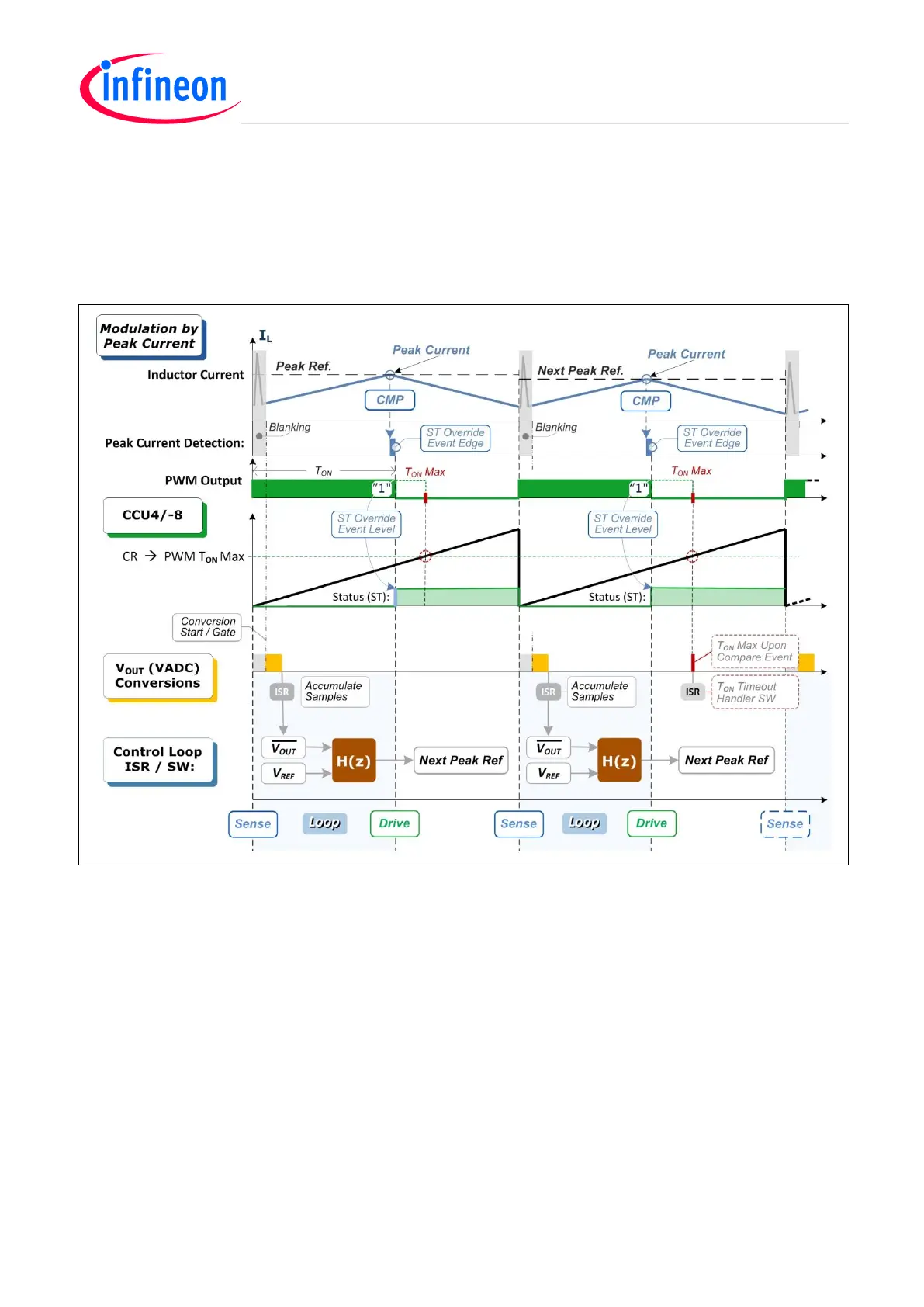
6.3.1 PCC Timing Scheme
The inherent PCC reflection is simplified here by a Status Bit (ST) Override operation in hardware on
a peak-detection by which the On-Time will be terminated in the PWM cycle. The Sense-Loop-Drive
process (marked by the blue background in the following diagram) is the peak reference control loop.
Figure 46 Peak Current Mode Control (PCC) - Max On-Time – Fixed Frequency (FF) – Timing
Note:
3. Because it has been simplified, the PCC illustrated here does not include the peak current reference Slope
Compensation technique.
4. Since there is a fixed frequency PWM (i.e. with a fixed cycle length), there is no need for an Off-Time limit.
However an On-Time limit is invoked by a timer compare (CR) level.
5. Noise should be rejected by disabling the analog comparator output by blanking control from a timer.
Steady State Frequency Response in the PCC Loop
The transfer function frequency response will be stabilized by compensating software, using DSP
operations on discrete time variables, maintained by the ISR that is stimulated by the VADC result
stream for the V
OUT
VC loop, triggered by a timer.

 Loading...
