Introduction to Digital Power Conversion
XMC4000/1000 Family
Control Loops
Application Guide 86 V1.0, 2015-01
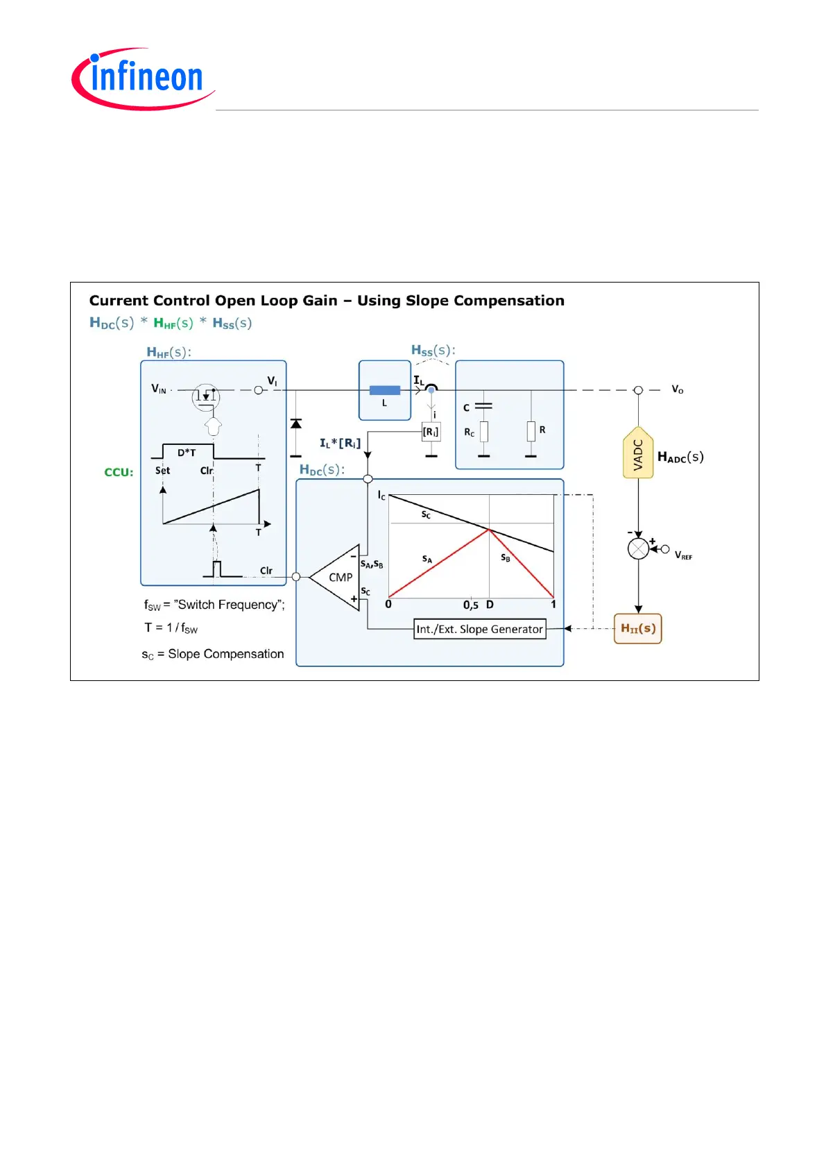
7.4.3 Open Loop Gain Current Mode w/ Slope Compensation
A representative principle of current mode control is chosen here: The Peak Current Control (PCC).
Slope Compensation is included, which has a prominent role in the dynamics of the open loop gain
‘played’ by the transfer functions (H
DC
* H
SS
). There is also, beside the ADC (H
ADC
), the in converters
ever recurring high-frequency function (H
HF
) and ultimate frequency compensation (H
II
).
Figure 70 Peak Current Mode Control (PCC) Open Loop Gain – Using Slope Compensation
H
SS
(s)
This stage senses the inductor (L) current I
L
with a DC gain (Ri/R) and a 1
st
order frequency function;
with 1 pole (due to the Slope Compensation operating point plus the RC-circuit damping factor) and 1
zero at 1/R
C
C (due to the time constant by the capacitor (C) and its ESR (R
C
) (See ESR in 7.4.1).
H
DC
(s)
This is a pure DC transfer function containing the Slope Compensation operating point damping
factor, the switch frequency (f
SW
) and the time constant (L/R), given by the inductor (L) and load (R)
circuit.
H
HF
(s)
This is the same type of high-frequency 2
nd
order transfer function as for all switch mode converters,
with a double-pole at half the switch frequency (½ f
SW
), i.e.
HF
= /T
SW
(See Figure 71).
H
II
(s)
The frequency compensation needs 2 poles and a zero to accomplish a nearly 20-dB/decade slope at
the 0-dB level crossing point for the desired stability by the appropriate phase margin and damping
factor.

 Loading...
