Introduction to Digital Power Conversion
XMC4000/1000 Family
PWM Generation
Application Guide 38 V1.0, 2015-01
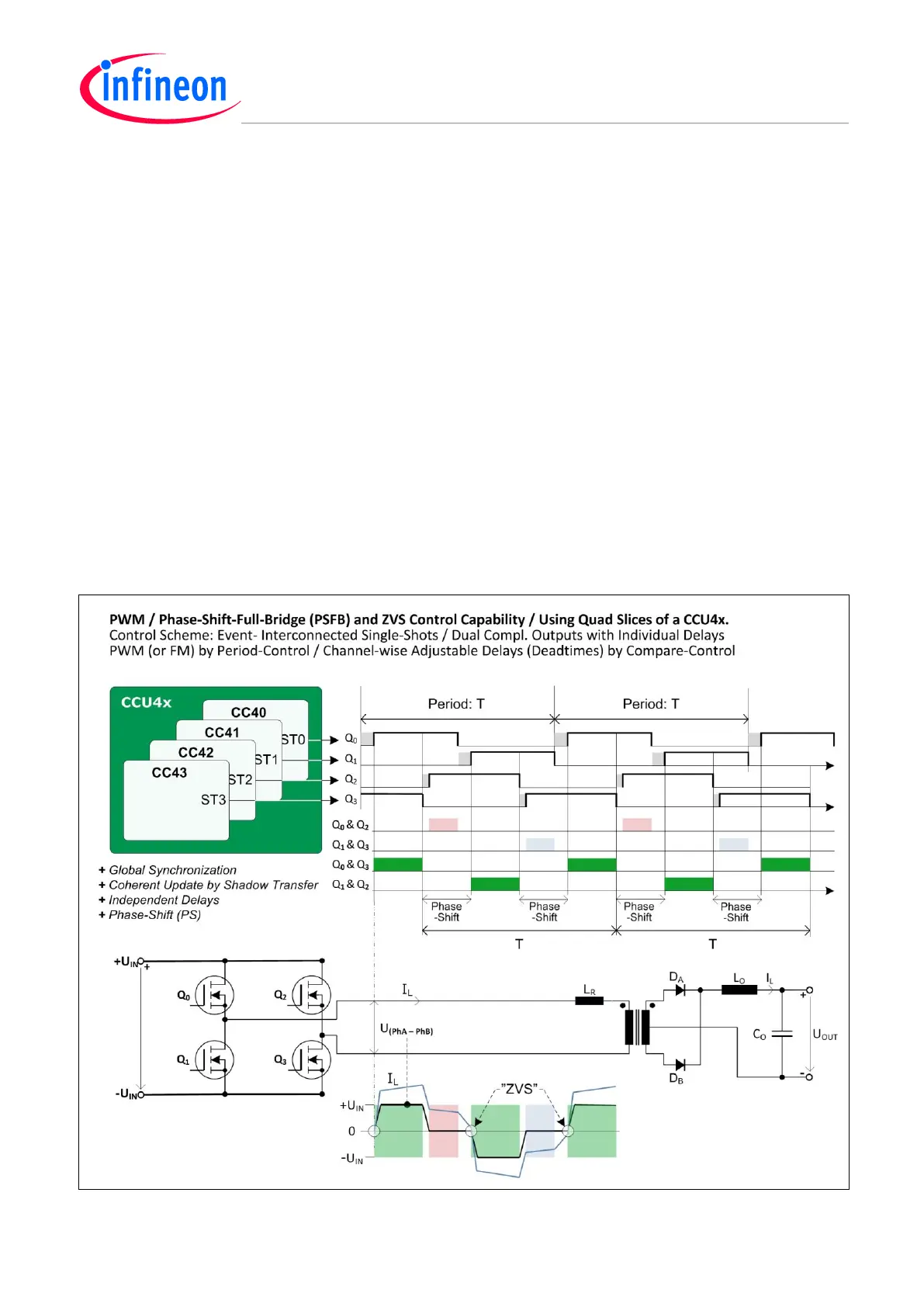
4.11.2 Zero-Voltage Switching (ZVS) Control
ZVS implies nearly lossless transitions. In combination with smooth zero crossing by resonance
components, an almost ideal switching process is achievable. This effect can be made by controlling
the free-wheeling currents and using the parasitic stray reactive elements (See also Figure 27).
Instead of using a traditional, combined control of the diagonal switches, there are individual delays
implemented to focus the ZVS spots to occur in appropriate time, and to keep the free-wheeling
current polarity unchanged.
Free-wheeling Current Control by Active Clamp
When the upper (or the lower) switches are conducting simultaneously, due to the phase shift, the
transformer and the free-wheeling inductive current path is short circuited to the upper (or lower) input
voltage rail.
The time-constant (‘L/R’) almost reaches infinity with this current on-holding active clamp.
ZVS Control
During the delay, in front of each turn-on event, the switch remains off and is clamped to a zero
voltage drop by the resonance effect.
The switch is held off while the free-wheeling current circulates via a body diode and the opposite leg
switch, still on. The inductive energy has to last for this though.
Figure 27 PWM – Phase-Shift-Full-Bridge (PSFB) with Zero-Voltage Switching (ZVS)

 Loading...
