Introduction to Digital Power Conversion
XMC4000/1000 Family
PWM Generation
Application Guide 24 V1.0, 2015-01
4 PWM Generation
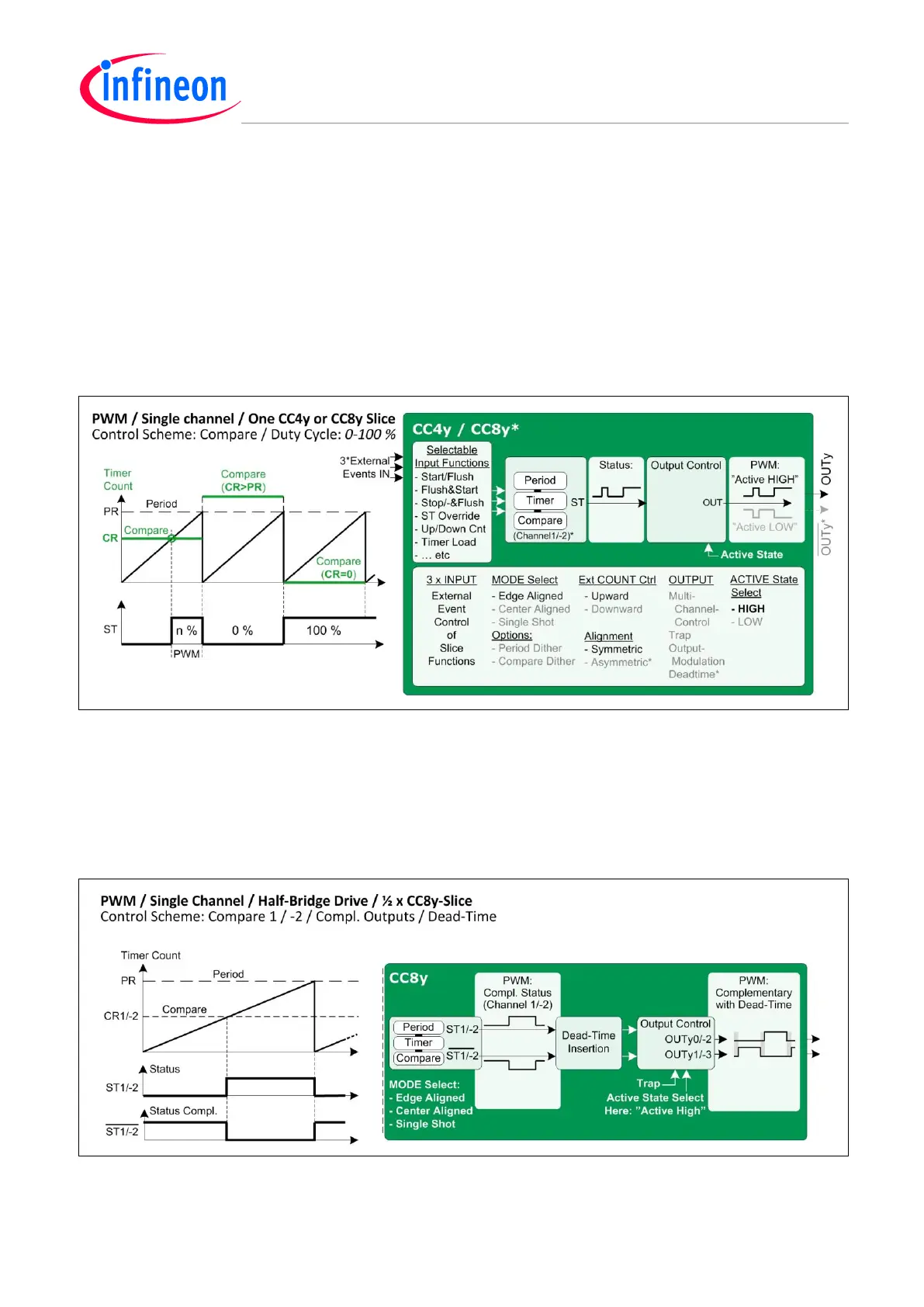
4.1 Single Channel
The PWM duty cycle range is 0 – 100% for all available combinations of alignments, count and
in/output modes.
Status bit ST can be set to 1 or 0 by timer compare or period events, or by external events (even if
stopped timer).
An output can be set active high or low (and with Dead-Time in CC8).
Figure 12 PWM – Single Channel
4.2 Single Channel with Complementary Outputs
A single channel (Ch1/-2) of a CC8y timer slice can output a complementary PWM signal pair in any
alignment mode. It may include Dead-Time Insertion of individual rise-/fall times, as well as accurate
active level settings for 1 or 2 half-bridges. The Trap input coordinates shut-down in correct real-time.
Figure 13 PWM – Single Channel Half-Bridge Drive

 Loading...
