Introduction to Digital Power Conversion
XMC4000/1000 Family
Modulation
Application Guide 60 V1.0, 2015-01
6.3 Peak Current Control (PCC)
The steady state duty-cycle-to-output transfer function in current control is maintained by two
essential control loops:
A fast inherent loop, reacting on limit current detections on a cycle-by-cycle basis
A slow coherent loop that reflects output versus reference deviation, adjusting the limit current
Steady State Transfer Function, using a Buck Converter topology
PCC can be realized differently, according to the XMC version and the available embedded analog
front-end with comparator capability (i.e. VADC in Fast-Compare mode, ACMP or a CSG with Slope
Generator).
The V
OUT
=D*V
IN
transfer function is maintained by a variable duty-cycle D (%) of the PWM cycles
(T).
The switch (Q) on-time (D*T) is cleared by a peak (or compare) current event.
The pulse stream from the CCU is either a Fixed Frequency (FF) PWM or a Fixed-Off-Time
(FOFFT), unfixed frequency PWM.
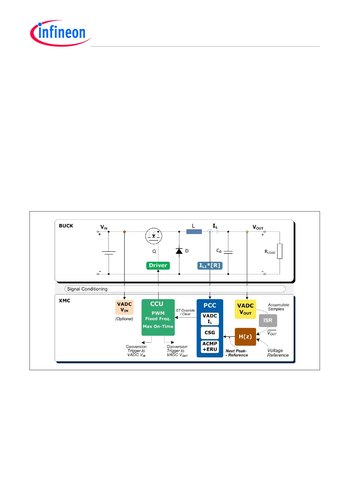
Figure 45 Peak Current Mode Control (PCC) – Max On-Time – Fixed Frequency (FF) – Example
Steady State DC PCC Loop
The long-term voltage mode control loop, based on ‘n’ VADC sensed samples, and accumulated by
the ISR, is a high-accuracy output voltage V
OUT
, with a fixed-target value relative to the voltage
reference. Any deviation is forced towards 0 by the feedback loop gain, setting a New Peak
Reference current.

 Loading...
