Introduction to Digital Power Conversion
XMC4000/1000 Family
Modulation
Application Guide 55 V1.0, 2015-01
6.2 Current Control
6.2.1 Average Current Control (ACC)
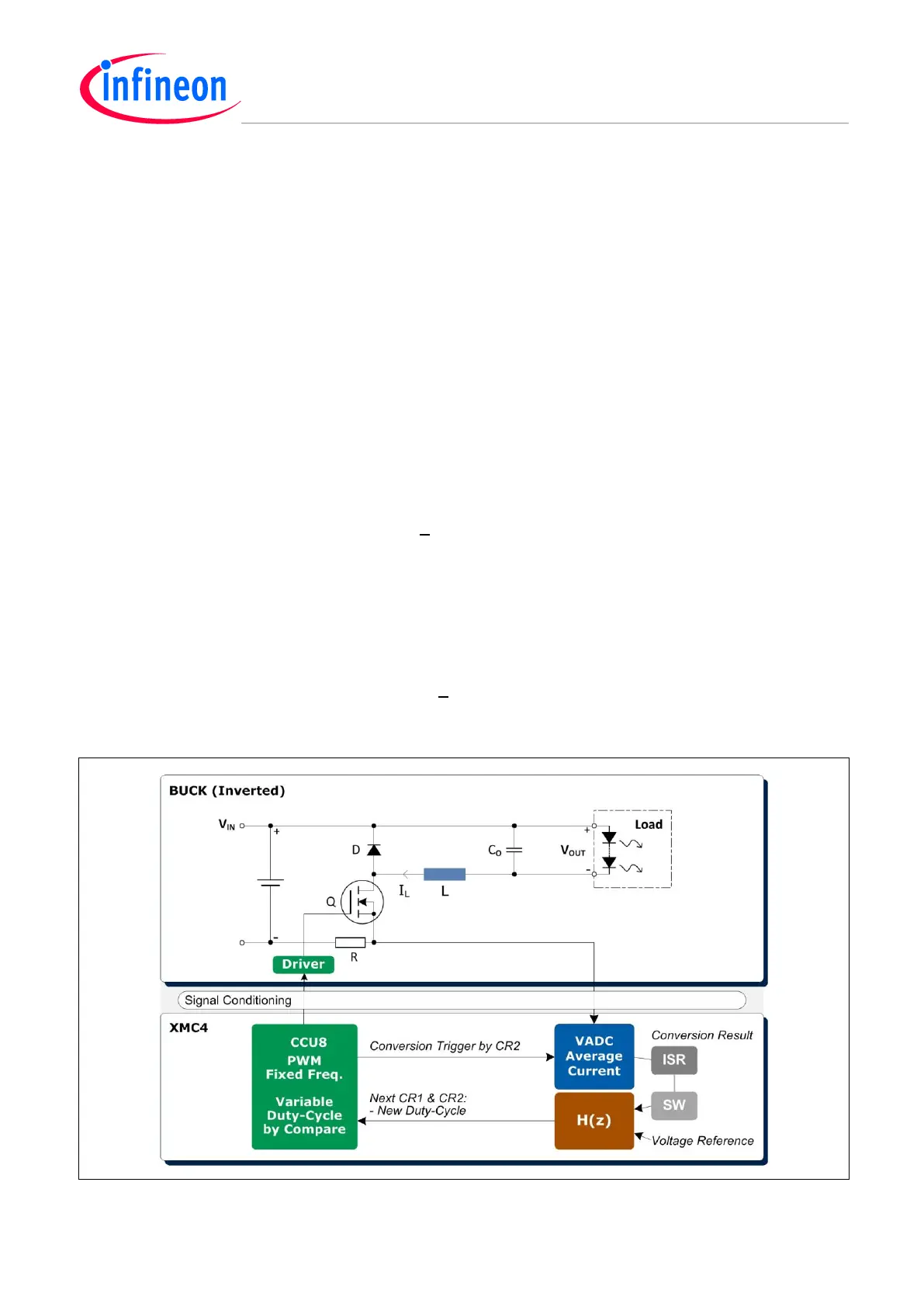
Reference Topology
Inversed Buck Converter.
A current generator, based on Average Current Control (ACC) of the inductor current, offers a voltage
drop between the supply rail and the load output that is nearly without any power loss, but might
cause some CPU load. The voltage drop is mainly covered by the inductor self-inductance.
An Inverse Buck converter has the benefit of making it possible to monitor the loop current in a very
easy and cost effective way. The current is monitored over a resistor’s (R) voltage drop (V
R
) to
ground.
Steady State Transfer Function
The steady state duty-cycle-to-output I
OUT
is the inductor (L) current (I
L
), consisting of a continuous
DC current plus/minus a ripple current within +
∆I
L
(where ∆I
L
=
DTV
L
/
L).
The duty-cycle D (%) of the PWM is the switch (Q) on-time; i.e. the maintaining variable in the ACC
loop.
T
= PWM cycle time.
V
L
= Inductor voltage = V
IN
- V
OUT
- V
Q
- V
R
or = - V
D
- V
OUT
, depending on if the switch (Q) is on or off,
respectively.
The voltage-drops V
Q
, V
R
(=I
L
*R) and V
D
might be negligible.
The I
OUT
current will ripple within I
L
= I
OUT
(Avrg) +
∆I
L
, as long as it is Continuous Conduction Mode
(CCM).
Figure 41 Average Current Mode Control – Using an Inverted Buck Converter for a LED Driver

 Loading...
