Introduction to Digital Power Conversion
XMC4000/1000 Family
Modulation
Application Guide 73 V1.0, 2015-01
Magnetic Voltage x Time (Vs) Balance Criteria
The stored magnetic energy in a homogeneous inductor volume V is:
½*B*H*V
B is the magnetic field density, flux [Voltage*Seconds/m
2
] and H is the magnetizing field [Amperes/m].
The loading and unloading of the inductor magnetic energy within two current levels is balanced if the
product of voltage (V
L+
) and time during energy loading is equal to the product of voltage (V
L-
) and
time during unloading the same amount of energy (See also Figure 57).
(V
L+
) * DT = (V
L-
) * (1-D-d)T.
D is duty-cycle (%)
T is PWM cycle time
d is discontinuous-current (%) of T, if it would occur (for example due to decreasing load), else d=0.
Average Current – Depending on the Current Conduction Mode
The only difference between CCM and CRM is a load dependent DC component level, while the
average DC level component by the peak-to-peak ripple current is equal. The DCM average current is
less than half the ripple amplitude, due to an affected duty-cycle by ‘d’ % discontinuous current time.
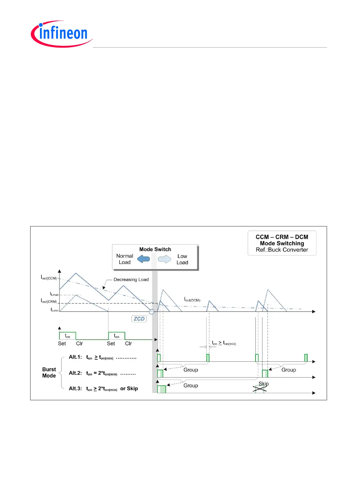
CCM, CRM and DCM switching on demand
Figure 58 CCM – CRM – DCM – Burst Mode Switching
CCM is usually suggested in high power applications.
CRM should not be used in 300W power applications or higher because EMI problems may
appear.
DCM is automatically entered when the load is decreasing so far that the current hits zero.
Burst should be used if the on-time (t
on
) becomes less than the t
on(min)
switch time of the MOSFET;
i.e. under very low, load conditions.

 Loading...
