LP340/340B/350 Service Manual 43
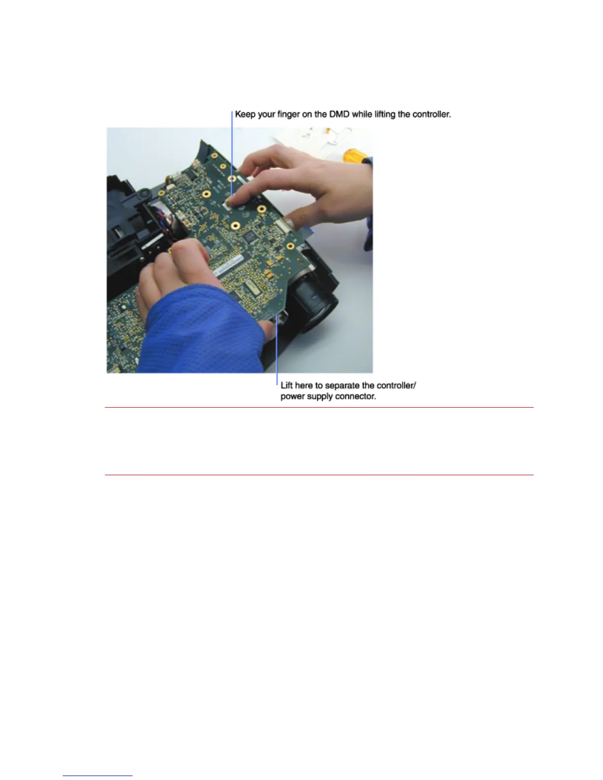
6 Place one finger on the top of the DMD. While keeping your finger on the DMD, carefully lift the
front of the controller ECA to disconnect the controller/power supply connector. Then remove the
controller ECA.
WARNING! Make sure you keep your finger on top of the DMD while lifting the controller ECA. The
DMD can stick to the bottom of the controller, and then fall off once the board is lifted. If the
DMD is damaged, the optical engine must be replaced. See page 62 for information about
reinstalling a DMD.
At this point you can read the DMD bias setting on the label on the back of the DMD. This setting
is required when you check and adjust the DMD bias setting on the controller ECA. Go to page
75, Updating the DMD Bias Setting.
Below is the label on the back of the DMD. The bias setting is A, B, C or D for the LP340/340B, or
B, C, D or E for the LP350. The bias setting in the example below is E.