Chapter 3 – Inputs-Outputs
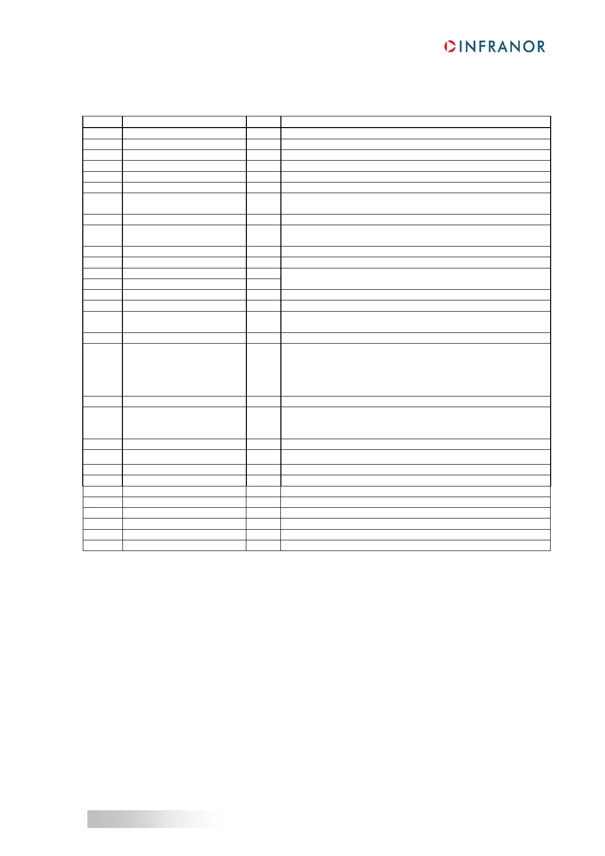
3 – X2: COMMAND CONNECTOR, LOGIC INPUTS-OUTPUTS AND ENCODER (Sub D 25 pins male)
Same connector for both 230 V and 400 V ranges.
Positive logic, optocoupled input, galvanic insulation
Positive logic, optocoupled input, galvanic insulation
Supply reference of the galvanic insulated logic inputs
Positive logic, optocoupled input, galvanic insulation
Supply reference of the galvanic insulated logic inputs
Positive logic, optocoupled input, galvanic insulation
CV0 Zero speed / Motor
phasing input command
Positive logic, optocoupled input, galvanic insulation
GND reference of the grounded drive
Positive logic, optocoupled input, galvanic insulation
Inhibition of the faults memory stored in the drive
Supply reference of the galvanic insulated logic inputs.
± 10 V speed input command for max. speed
or ± 10 V current input command for Imax with "CI" input active
GND reference of the earthed drive
I limit current limitation
Analog input for external max. current limitation
0 to 10 V for 100 % to 0 % of Imax
+/-10 V, resolution: 8 bit, load: 10 mA, linearity: 2 %, low pass
filter: 170 Hz, programmable output signal: Channel 1 of the
digital oscilloscope (current, speed or position) or Phasing OK
output (from 0 V to 10 V when the motor phasing is OK for an
incremental encoder without HES)
Relay contact: closed if drive OK, open if fault.
Protection against overvoltages by bidirectional TRANSIL
Pmax = 10 W with Umax = 50 V or Imax = 100 mA
Output impedance: 9 Ohms. Max. 150 mA available
(1)
Output impedance: 47 Ohms. Max. 50 mA available
Differential output of Z/ encoder marker pulse (max. 5 V, 20 mA)
Differential output of Z encoder marker pulse (max. 5 V, 20 mA)
Differential output of encoder A/ channel (max. 5 V, 20 mA)
Differential output of encoder A channel (max. 5 V, 20 mA)
Differential output of encoder B/ channel (max. 5 V, 20 mA)
Differential output of encoder B channel (max. 5 V, 20 mA)
(1): The sum of the currents consumed by both X2 connector, pin 21, and X3 connector, pin 10, must not
exceed 150 mA.



 To Next Page