Chapter 3 – Inputs-Outputs
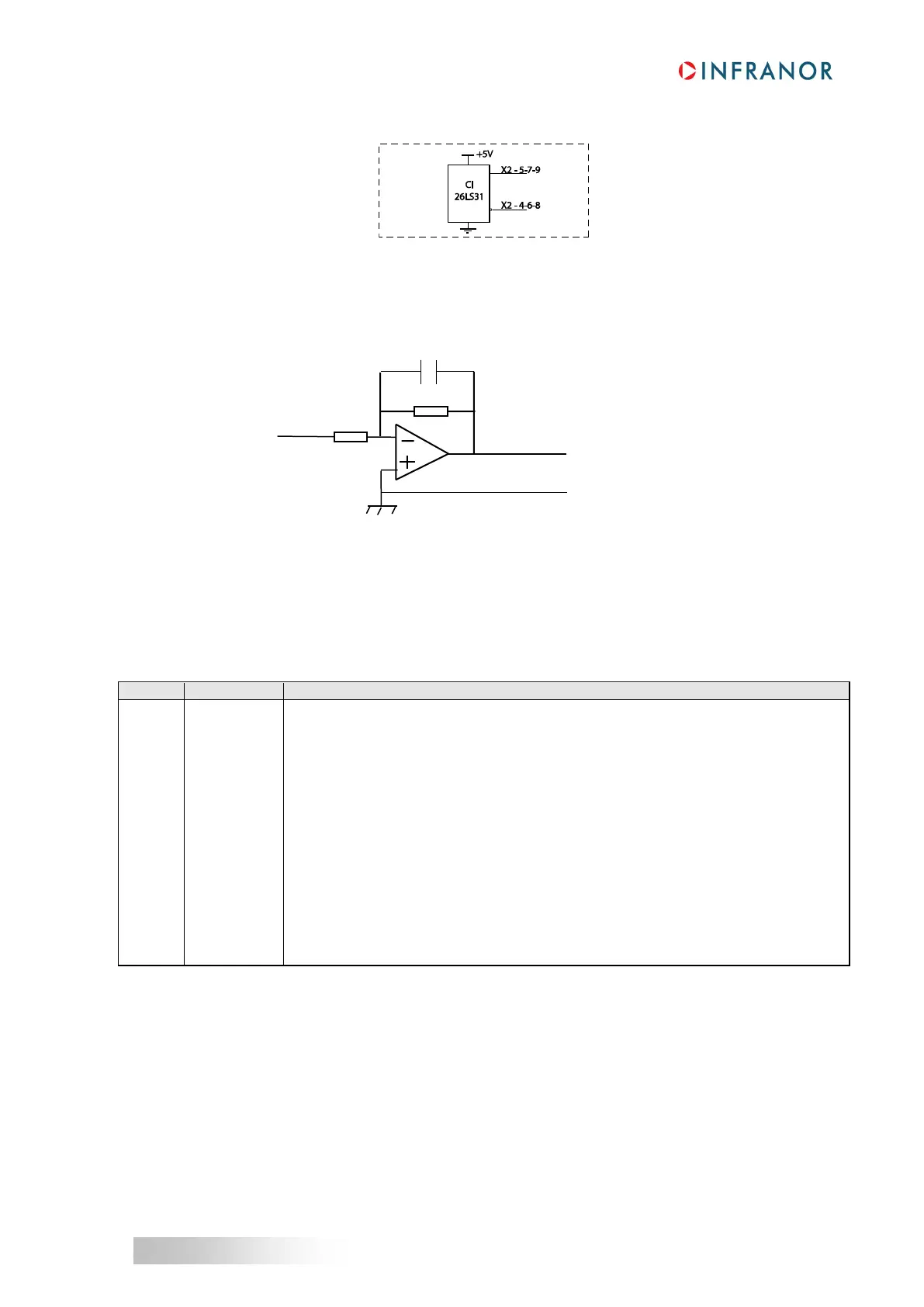
3.4 - SPECIFICATION OF THE ENCODER OUTPUTS
Recommended receiver: 26LS32
3.5 - SPECIFICATION OF THE ANALOG OUTPUT
4 - X3 ENCODER INPUT
Same connector for both 230 V and 400 V ranges.
4.1 - X3 CONNECTOR FOR TTL INCREMENTAL ENCODER & HES INPUT (Sub D 25 pins female)
The “TTL incremental encoder & HES” configuration is selectable by software and stored into the drive EEPROM.
The corresponding X3 connector pin functions are described below.
Differential input of the encoder marker pulse Z/
Differential input of the encoder marker pulse Z
Differential input of the encoder channel A/
Differential input of the encoder channel A
Differential input of the encoder channel B/
Differential input of the encoder channel B
Encoder supply voltage (300 mA max. current)
Hall sensor input signal phase U
Hall sensor input signal phase V
Hall sensor input signal phase W
Hall sensors supply voltage: output impedance = 9 Ω, max 150 mA available
(1)
Motor thermal sensor input
Motor thermal sensor input
(1): The sum of the currents consumed by both X2 connector, pin 21, and X3 connector, pin 10,must not exceed
150 mA.

 Loading...