3.2 - I
2
t PROTECTION
2 selection modes are available: Fusing or Limiting.
It is advisable to use the Fusing mode during commissioning phases.
In Fusing mode, the drive is disabled when the current limitation threshold is reached.
In Limiting mode, the motor current is only limited at the value defined by the Rated current parameter when the
limitation threshold is reached.
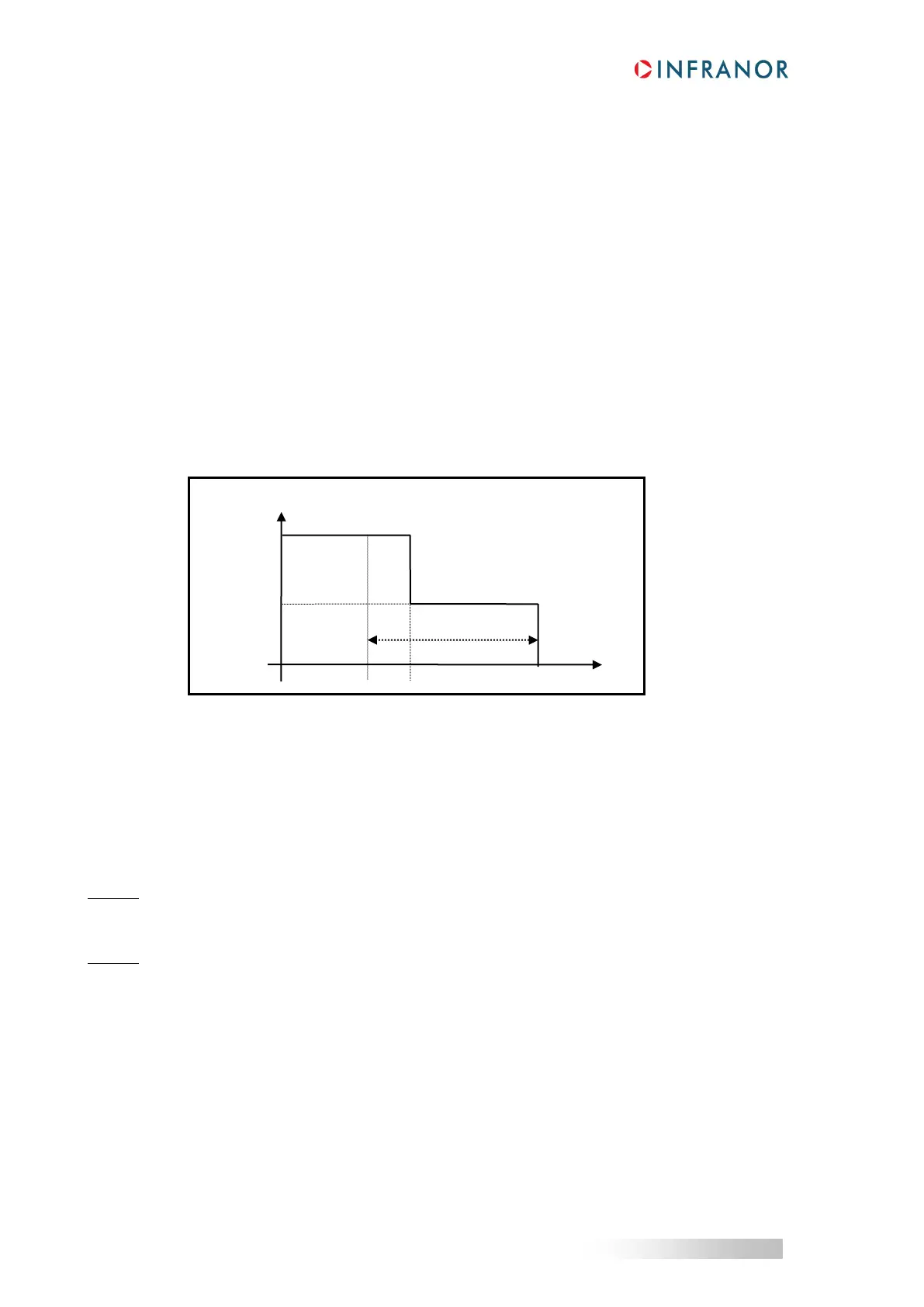
3.2.1 - OPERATION OF THE CURRENT LIMITATION IN FUSING MODE
When the drive output RMS current (I
2
t) reaches 85 % of the rated current, the I²t fault LED is blinking on the
drive front panel (t1 in the diagram). If the RMS current (I
2
t) has not dropped below 85 % of the rated current
within 1 second, the I
2
t error is released and the drive disabled, otherwise, the blinking is inhibited (t3 in the
diagram).
When the drive output RMS current (I
2
t) reaches the rated current value, the I
2
t limits the drive output current at
this value (t2 in the diagram).
Diagram of the drive output current limitation in an extreme case (motor overload or shaft locked):
The maximum current duration before release of the blinking display is depending on the value of the parameters
Rated current and Max. current. This value is calculated as follows:
T
dyn
(second) = t
1
-t
0
= 3,3 x Rated current (A) / Max. current (A)
2
The maximum current duration before limitation at the rated current is also depending on the value of the Rated
current and Maximum current parameters. This value is calculated as follows:
T
max
(second) = t
2
-t
0
= 4 x Rated current (A) / Max. current (A)
2
NOTE 1
When the "Max. current / Rated current" ratio is equal to 1, the I²t error is never released. But these formulas
remain very precise as long as the "Max. current / Rated current" ratio is higher than 3/2.
NOTE 2
The drive I
2
t signal can be displayed on the digital oscilloscope by selecting the I
2
t signal in the Channel menu.
The threshold values of the I
2
t signal, for the protection mode described above, are calculated as follows:
Current limitation threshold (%) = Rated current (%)
2
/ 50
Rated current (%) = 100 x Rated current (A) / drive current rating (A)
The corresponding RMS current value of the drive can be calculated as follows:
Drive RMS current (A) = I
2
t signal value (%) x 50
1/2
x
drive current rating (A) / 100
t1 = Blinking
t2 = Current limitation
t3 = I
2
t error